Showing posts with label Rohde and Schwarz. Show all posts

Wednesday, May 31, 2023

New 5G NTN Spectrum Bands in FR1 and FR2

Release-17 includes two new FR1 bands for NTN; n255 (a.k.a. NTN 1.6GHz) and n256 (a.k.a. NTN 2GHz). The picture is from a slide in Rohde & Schwarz presentation available here. Quoting from an article by Reiner Stuhlfauth, Technology Manager Wireless, Rohde & Schwarz:

Currently, several frequency ranges are being discussed within 3GPP for NTN. Some are in the FR1 legacy spectrum, and some beyond 10 GHz and FR2. The current FR1 bands discussed for NTN are:

  • The S-band frequencies from 1980 to 2010 MHz in uplink (UL) direction and from 2170 to 2200 MHz in downlink (DL) direction (Band n256).
  • The L-band frequencies from 1525 to 1559 MHz DL together with 1626.5 to 1660.5 MHz for the UL (Band n255).1

These frequency ranges have lower path attenuation, and they’re already used in legacy communications. Thus, components are available now, but the bands are very crowded, and the usable bandwidth is restricted. Current maximum bandwidth is 20 MHz with up to 40-MHz overall bandwidth envisaged in the future [TR 38.811].

As far as long-term NTN spectrum use is concerned, 3GPP is discussing NR-NTN above 10 GHz. The Ka-band is the highest-priority band with uplinks between 17.7 and 20.2 GHz and downlinks between 27.5 and 30 GHz, based on ITU information regarding satellite communications frequency use.2 Among current FR2 challenges, one is that some of the discussed bands fall into the spectrum gap between FR1 and FR2 and that NTN frequencies will use FDD duplex mode due to the long roundtrip time.

Worth highlighting again that the bands above, including n510, n511 and n512 are all FDD bands due to the long round trip times.

The latest issue of 3GPP highlight magazine has an article on NTN as well. Quoting from the article:

The NTN standard completed as part of 3GPP Release 17 defines key enhancements to support satellite networks for two types of radio protocols/interfaces:

  • 5G NR radio interface family also known as NR-NTN
  • 4G NB-IoT & eMTC radio interfaces family known as IoT-NTN

These critical enhancements including adaptation for satellite latency and doppler effects have been carefully defined to support a wide range of satellite network deployment scenarios and orbits (i.e., LEO, MEO and GEO), terminal types (handheld, IoT, vehicle mounted), frequency bands, beam types (Earth fixed/Earth moving) and sizes. The NTN standard also addresses mobility procedures across both terrestrial and non-terrestrial network components. Release 17 further includes Radio Frequency and Radio Resource Management specifications for terminals and satellite access nodes operating in two FR1 frequency ranges allocated to Mobile Satellite Services (i.e., n255 and n256).

You can read it here.

Related Posts

Friday, October 23, 2020

Positioning Techniques for 5G NR in 3GPP Release-16

I realised that I have not looked at Positioning techniques a lot in our blogs so this one should be a good summary of the latest positioning techniques in 5G.

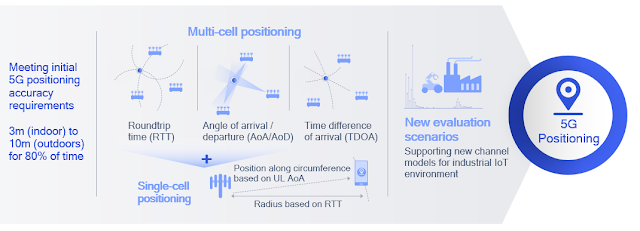
Qualcomm has a nice short summary hereRelease 16 supports multi-/single-cell and device-based positioning, defining a new positioning reference signal (PRS) used by various 5G positioning techniques such as roundtrip time (RTT), angle of arrival/departure (AoA/AoD), and time difference of arrival (TDOA). Roundtrip time (RTT) based positioning removes the requirement of tight network timing synchronization across nodes (as needed in legacy techniques such as TDOA) and offers additional flexibility in network deployment and maintenance. These techniques are designed to meet initial 5G requirements of 3 and 10 meters for indoor and outdoor use cases, respectively. In Release 17, precise indoor positioning functionality will bring sub-meter accuracy for industrial IoT use cases.

I wrote about the 5G Americas white paper titled, "The 5G Evolution: 3GPP Releases 16-17" highlighting new features in 5G that will define the next phase of 5G network deployments across the globe. The following is from that whitepaper:

Release-15 NR provides support for RAT-independent positioning techniques and Observed Time Difference Of Arrival (OTDOA) on LTE carriers. Release 16 extends NR to provide native positioning support by introducing RAT-dependent positioning schemes. These support regulatory and commercial use cases with more stringent requirements on latency and accuracy of positioning.25 NR enhanced capabilities provide valuable, enhanced location capabilities. Location accuracy and latency of positioning schemes improve by using wide signal bandwidth in FR1 and FR2. Furthermore, new schemes based on angular/spatial domain are developed to mitigate synchronization errors by exploiting massive antenna systems.

The positioning requirements for regulatory (e.g. E911) and commercial applications are described in 3GPP TR 38.855. For regulatory use cases, the following are the minimum performance requirements:

  • Horizontal positioning accuracy better than 50 meters for 80% of the UEs.
  • Vertical positioning accuracy better than 5 meters for 80% of the UEs.
  • End-to-end latency less than 30 seconds.

For commercial use cases, for which the positioning requirements are more stringent, the following are the starting-point performance targets

  • Horizontal positioning accuracy better than 3 meters (indoors) and 10 meters (outdoors) for 80% of the UEs.
  • Vertical positioning accuracy better than 3 meters (indoors and outdoors) for 80% of the UEs.
  • End-to-end latency less than 1 second.

Figure 3.11 above shows the RAT-dependent NR positioning schemes being considered for standardization in Release 16:

  • Downlink time difference of arrival (DL-TDOA): A new reference signal known as the positioning reference signal (PRS) is introduced in Release 16 for the UE to perform downlink reference signal time difference (DL RSTD) measurements for each base station’s PRSs. These measurements are reported to the location server.
  • Uplink time difference of arrival (UL-TDOA): The Release-16 sounding reference signal (SRS) is enhanced to allow each base station to measure the uplink relative time of arrival (UL-RTOA) and report the measurements to the location server.
  • Downlink angle-of-departure (DL-AoD): The UE measures the downlink reference signal receive power (DL RSRP) per beam/gNB. Measurement reports are used to determine the AoD based on UE beam location for each gNB. The location server then uses the AoDs to estimate the UE position.
  • Uplink angle-of-arrival (UL-AOA): The gNB measures the angle-of-arrival based on the beam the UE is located in. Measurement reports are sent to the location server.
  • Multi-cell round trip time (RTT): The gNB and UE perform Rx-Tx time difference measurement for the signal of each cell. The measurement reports from the UE and gNBs are sent to the location server to determine the round trip time of each cell and derive the UE position.
  • Enhanced cell ID (E-CID). This is based on RRM measurements (e.g. DL RSRP) of each gNB at the UE. The measurement reports are sent to the location server.

UE-based measurement reports for positioning:

  • Downlink reference signal reference power (DL RSRP) per beam/gNB
  • Downlink reference signal time difference (DL RSTD)
  • UE RX-TX time difference

gNB-based measurement reports for positioning:

  • Uplink angle-of-arrival (UL-AoA)
  • Uplink reference-signal receive power (UL-RSRP)
  • UL relative time of arrival (UL-RTOA)
  • gNB RX-TX time difference

NR adopts a solution similar to that of LTE LPPa for Broadcast Assistance Data Delivery, which provides support for A-GNSS, RTK and OTDOA positioning methods. PPP-PTK positioning will extend LPP A-GNSS assistance data message based on compact “SSR messages” from QZSS interface specifications. UE-based RAT-dependent DL-only positioning techniques are supported, where the positioning estimation will be done at the UE-based on assistance data provided by the location server.


Rohde&Schwarz have a 5G overview presentation here. This picture from that presentation is a good summary of the 3GPP Release-16 5G NR positioning techniques. This nice short video on "Release 16 Location Based Services Requirements" complements it very well. 


Related Posts:

Monday, July 27, 2020

Key Technology Aspects of 5G Security by Rohde & Schwarz


The 3G4G page contains a lot of useful papers and links to security here but we have also looked at evolution of security from 4G to 5G here. Rohde & Schwarz has a short 8-minute video in which wireless technology manager, Reiner Stuhlfauth, explains the key technology aspects ensuring 5G security. The video is embedded below.


Related Links:

Tuesday, May 19, 2020

5G Dynamic Spectrum Sharing (DSS)

5G Dynamic Spectrum Sharing is a hot topic. I have already been asked about multiple people for links on good resources / whitepapers. So here is what we liked, feel free to add anything else you found useful as part of comments.


Nokia has a nice high level overview of this topic which is available here. I really liked the decision tree as shown in the tweet above. I am going to quote a section here that is a great summary to decide if you want to dive deeper.

DSS in the physical layer
DSS allows CSPs to share resources dynamically between 4G and 5G in time and/or frequency domains, as shown on the left of Figure 3. It’s a simple idea in principle, but we also need to consider the detailed structure at the level of the resource block in order to understand the resource allocations for the control channels and reference signals. A single resource block is shown on the right side of Figure 3.

The 5G physical layer is designed to be so similar to 4G in 3GPP that DSS becomes feasible with the same subcarrier spacing and similar time domain structure. DSS is designed to be backwards compatible with all existing LTE devices. CSPs therefore need to maintain LTE cell reference signal (CRS) transmission. 5G transmission is designed around LTE CRS in an approach called CRS rate matching.

5G uses demodulation reference signals (DMRS), which are only transmitted together with 5G data and so minimize any impact on LTE capacity. If all LTE devices support Transmission Mode 9 (TM9), then the shared carrier has lower overheads because less CRS transmission is required. The control channel transmission and the data transmission can be selected dynamically between LTE and 5G, depending on the instantaneous capacity requirements.


The second resource is this Rohde & Schwarz webinar here. As can be seen in the tweet above, it provides nice detailed explanation.

Finally, we have a Comprehensive Deployment Guide to Dynamic Spectrum Sharing for 5G NR and 4G LTE Coexistence, which is a nice and detailed whitepaper from Mediatek. Quoting a small section from the WP for anyone not wanting to go too much in deep:

The DSS concept is based on the flexible design of NR physical layer. It uses the idea that NR signals are transmitted over unused LTE resources. With LTE, all the channels are statically assigned in the time-frequency domain, whereas the NR physical layer is extremely flexible for reference signals, data and control channels, thus allowing dynamic configurations that will minimize a chance of collision between the two technologies. 

One of the main concepts of DSS is that only 5G users are made aware of it, while the functionalities of the existing LTE devices remain unaffected (i.e. LTE protocols in connected or idle mode). Therefore, fitting the flexible physical layer design of NR around that of LTE is needed in order to deploy DSS on a shared spectrum. This paper discusses the various options of DSS implementation, including deployment challenges, possible impacts to data rates, and areas of possible improvements.

NR offers a scalable and flexible physical layer design depicted by various numerologies. There are different subcarrier spacing (SCS) for data channels and synchronization channels based on the band assigned. This flexibility brings even more complexity because it overlays the NR signals over LTE, which requires very tight coordination between gNB and eNB in order to provide reliable synchronization in radio scheduling.

The main foundation of DSS is to schedule NR users in the LTE subframes while ensuring no respective impact on LTE users in terms of essential channels, such as reference signals used for synchronization and downlink measurements. LTE Cell Reference Signals (CRS) is typically the main concept where DSS options are designated, as CRS have a fixed time-frequency resource assignment. The CRS resources layout can vary depending on the number of antenna ports. More CRS antenna ports leads to increased usage of Resource Elements (REs). CRS generates from 4.76% (1 antenna port) up to 14.29% (4 antenna ports) overhead in LTE resources. As CRS is the channel used for downlink measurements, avoiding possible collision with CRS is one of the foundations of the DSS options shown in figure 1. The other aspect of DSS design is to fit the 5G NR reference signals within the subframes in a way to avoid affecting NR downlink measurements and synchronization. For that, DSS considers the options shown in figure 1 to ensure NR reference signals such as Synchronization Signal Block (SSB) or Demodulation Reference Signal (DMRS) are placed in time-frequencies away from any collision with LTE signals.

MBSFN, option 1 in figure 1, stands for Multi-Broadcast Single-Frequency Network and is used in LTE for point-to-multipoint transmission such as eMBMS (Evolved Multimedia Broadcast Multicast Services). The general idea of MBSFN is that specific subframes within an LTE frame reserve the last 12 OFDM symbols of such subframe to be free from other LTE channel transmission. These symbols were originally intended to be used for broadcast services and are “muted” for data transmission in other LTE UE. Now this idea has been adjusted for use in a DSS concept, so that these reserved symbols are used for NR signals instead of eMBMS. While in general LTE PDCCH can occupy from 1 to 3 symbols (based on cell load), the first two OFDM symbols of such MBSFN subframe are used for LTE PDCCH, and DSS NR UE can use the third symbol. Using MBSFN is completely transparent to legacy LTE-only devices from 3GPP Release 9 onwards, as such LTE UE knows that these subframes are used for other purposes. In this sense this is the simplest way of deploying DSS. This method has disadvantages though. The main one is that if MBSFN subframes are used very frequently and it takes away resources from LTE users, heavily reducing LTE-only user throughput. Note that option 1 shown in figure 1 does not require LTE MBSFN Reference Signals to be used, because the MBSFN subframe is used to mute the subframe for DSS operation only, and LTE CRS shall only be transmitted in the non-MBSFN region (within the first two symbols) of the MBSFN subframe.

The two other options illustrated in figure 1 are dealing with non-MBSFN subframes that contain LTE reference signals. Option 2 is ‘mini-slot’ based; mini-slot scheduling is available in NR for URLLC applications that require extremely low latency. The symbols can be placed anywhere inside the NR slot. In respect to DSS, mini-slot operation just eliminates the usage of the symbols that contain LTE CRS and schedule only free ones for NR transmission. The basic limitation of this method comes from the concept itself. It is not very suitable for eMBB applications as too many resources are outside of NR scheduling. However it still can be utilized in some special cases like 30 kHz SSB insertion which will be described later in this paper.

Option 3 is based on CRS rate matching in non-MBSFN subframes, and it is expected to be the one most commonly used for NR data channels. In this option, the UE performs puncturing of REs used by LTE CRS so that the NR scheduler knows which REs are not available for NR data scheduling on PDSCH (Physical Downlink Shared Channel). The implementation of this option can be either Resource Block (RB)-level when the whole RB containing LTE CRS is taken out of NR scheduling, or RE-level where NR PDSCH scheduling avoids particular REs only. The end result of this method is that the scheduler will reduce the NR PDSCH transport block size as the number of REs available for scheduling become less in a slot.


Personally, I am not a big fan of DSS mainly because I think it is only useful in a very few scenarios. Also, it helps operators show a 5G logo but doesn't provide a 5G experience by itself. Nevertheless, it can come in handy for the coverage layer of 5G.


In one of the LinkedIn discussions (that I try and avoid mostly) somebody shared this above picture of Keysight Nemo DSS lab test results. As you can see there is quite a bit of overhead with DSS.

Sunday, October 27, 2019

R&S Webinar on LTE-A Pro and evolution to 5G


Rohde & Schwarz recently uploaded a webinar video on their YouTube channel. I found it really useful. It's embedded below.

Topics covered:

  • LTE-M / NB-IoT
    • feMTC
    • UE Category M2
    • OTDOA based positioning
  • UE Categories
  • Unlicensed Spectrum Overview
  • LTE in Unlicensed Spectrum
    • LWA, LWIP
    • LAA, eLAA
    • Wi-Fi
    • LBT
    • LWA mobility
  • Carrier Aggregation Enhancements
  • Multi-user superposition transmission (MUST)
  • Single cell - point to multipoint transmission (SC-PTM)
    • SC-PTM Channel Structure
    • SC-PTM Channel Flow
  • Massive MIMO
  • V2X Overview
    • eNB scheduling - transmission mode 3
    • Distributed scheduling - transmission mode 4
    • Direct communication
  • LTE Advanced Pro (Release 15)
    • Further NB-IoT Enhancements
    • Even further enhanced MTC - eMTC4 (Rel-15)


Related Posts:

Monday, October 8, 2018

Wi-Fi gets new name


Wi-Fi Alliance has announced that the next generation WiFi technology, 802.11ax, will be known as Wi-Fi 6. This is to probably make it simpler, similar to mobile technology generations. Everyone knows 3G and 4G but how many people know UMTS or LTE. Similarly they are hoping that people will be aware of Wi-Fi 4, 5 & 6. They haven't bothered to name anything below Wi-Fi 4.


Looking at this picture from R&S above, you can see that according to Wi-Fi Alliance naming convention:

Wi-Fi 1: 802.11a (1999)
Wi-Fi 2: 802.11b (1999)
Wi-Fi 3: 802.11g (2003)
Wi-Fi 4: 802.11n (2009)
Wi-Fi 5: 802.11ac (2014)
Wi-Fi 6: 802.11ax (2019)

Anyway, I am not going in any technical details in this post but look for the really good links on this topic below.

To learn more about the naming of next-gen Wi-Fi, check this link.

Further reading:

Saturday, November 12, 2016

Verizon's 5G Standard

Earlier this year I wrote a Linkedin post on how operators are setting a timetable for 5G (5G: Mine is bigger than yours) and recently Dean Bubley of Disruptive Analysis wrote a similar kind of post also on Linkedin with a bit more detail (5G: Industry Politics, Use-Cases & a Realistic Timeline)


Some of you may be unaware that the US operator Verizon has formed 'Verizon 5G Technology Forum' (V5GTF) with the intention of developing the first set of standards that can also influence the direction of 3GPP standardization and also provide an early mover advantage to itself and its partners.

The following from Light Reading news summarizes the situation well:

Verizon has posted its second round of work with its partners on a 5G specification. The first round was around the 5G radio specification; this time the work has been on the mechanics of connecting to the network. The operator has been working on the specification with Cisco Systems Inc., Ericsson AB, Intel Corp., LG Electronics Inc., Nokia Corp., Qualcomm Inc. and Samsung Corp. via the 5G Technology Forum (V5GTF) it formed late in 2015.

Sanyogita Shamsunder, director of strategy at Verizon, says that the specification is "75% to 80% there" at least for a "fixed wireless use case." Verizon is aiming for a "friendly, pre-commercial launch" of a fixed wireless pilot in 2017, Koeppe notes.

Before we go further, lets see this excellent video by R&S wherein Andreas Roessler explains what Verizon is up to:


Verizon and SKT are both trying to be the 5G leaders and trying to roll out a pre-standard 5G whenever they can. In fact Qualcomm recently released a 28 GHz modem that will be used in separate pre-standard 5G cellular trials by Verizon and Korea Telecom

Quoting from the EE times article:

The Snapdragon X50 delivers 5 Gbits/second downlinks and multiple gigabit uplinks for mobile and fixed-wireless networks. It uses a separate LTE connection as an anchor for control signals while the 28 GHz link delivers the higher data rates over distances of tens to hundreds of meters.

The X50 uses eight 100 MHz channels, a 2x2 MIMO antenna array, adaptive beamforming techniques and 64 QAM to achieve a 90 dB link budget. It works in conjunction with Qualcomm’s SDR05x mmWave transceiver and PMX50 power management chip. So far, Qualcomm is not revealing more details of modem that will sample next year and be in production before June 2018.

Verizon and Korea Telecom will use the chips in separate trials starting late next year, anticipating commercial services in 2018. The new chips mark a departure from prototypes not intended as products that Qualcomm Research announced in June.

Korea Telecom plans a mobile 5G offering at the February 2018 Winter Olympics. Verizon plans to launch in 2018 a less ambitious fixed-wireless service in the U.S. based on a specification it released in July. KT and Verizon are among a quartet of carriers that formed a group in February to share results of early 5G trials.

For its part, the 3GPP standards group is also stepping up the pace of the 5G standards efforts it officially started earlier this year. It endorsed last month a proposal to consider moving the date for finishing Phase I, an initial version of 5G anchored to LTE, from June 2018 to as early as December 2017, according to a recent Qualcomm blog.

Coming back to Verizon's 5G standard, is it good enough and compatible with 3GPP standards? The answer right now seems to be NO.


The following is from Rethink Wireless:

The issue is that Verizon’s specs include a subcarrier spacing value of 75 kHz, whereas the 3GPP has laid out guidelines that subcarrier spacing must increase by 30 kHz at a time, according to research from Signals Research Group. This means that different networks can work in synergy if required without interfering with each other.

Verizon’s 5G specs do stick to 3GPP requirements in that it includes MIMO and millimeter wave (mmWave). MmWave is a technology that both AT&T and Verizon are leading the way in – which could succeed in establishing spectrum which is licensed fairly traditionally as the core of the US’s high frequency build outs.

A Verizon-fronted group recently rejected a proposal from AT&T to push the 3GPP into finalizing an initial 5G standard for late 2017, thus returning to the original proposed time of June 2018. Verizon was supported by Samsung, ZTE, Deutsche Telecom, France Telecom, TIM and others, which were concerned the split would defocus SA and New Radio efforts and even delay those standards being finalized.

Verizon has been openly criticized in the industry, mostly by AT&T (unsurprisingly), as its hastiness may lead to fragmentation – yet it still looks likely to beat AT&T to be the first operator to deploy 5G, if only for fixed access.

Verizon probably wants the industry to believe that it was prepared for eventualities such as this – prior to the study from Signal Research Group, the operator said its pre-standard implementation will be close enough to the standard that it could easily achieve full compatibility with simple alterations. However, Signals Research Group’s president Michael Thelander has been working with the 3GPP since the 5G standard was birthed, and he begs to differ.

Thelander told FierceWireless, “I believe what Verizon is doing is not hardware-upgradeable to the real specification. It’s great to be trialing, even if you define your own spec, just to kind of get out there and play around with things. That’s great and wonderful and hats off to them. But when you oversell it and call it 5G and talk about commercial services, it’s not 5G. It’s really its own spec that has nothing to do with Release 16, which is still three years away. Just because you have something that operates in millimeter wave spectrum and uses Massive MIMO and OFDM, that doesn’t make it a 5G solution.”

Back in the 3G days, NTT Docomo was the leader in standards and it didn't have enough patience to wait for 3GPP standards to complete. As a result it released its first 3G network called FOMA (Freedom of Mobile Access) based on pre-standard version of specs. This resulted in handset manufacturers having to tweak their software to cope with this version and it suffered from economy of scale. Early version of 3G phones were also not able to roam on the Docomo network. In a way, Verizon is going down the same path.

While there can be some good learning as a result of this pre-5G standard, it may be a good idea not to get too tied into it. A standard that is not compliant will not achieve the required economy of scale, either with handsets or with dongles and other hotspot devices.


Related posts:


Wednesday, August 10, 2016

New whitepaper on Narrowband Internet of Things

Rohde & Schwarz has just published a new whitepaper on Narrowband Internet of Things (NB-IoT).

NB-IoT has been introduced as part of 3GPP Rel-13 where 3GPP has specified a new radio interface. NBIoT is optimized for machine type traffic and is kept as simple as possible in order to reduce device costs and to minimize battery consumption. In addition, it is also adapted to work in difficult radio conditions, which is a frequent operational area for certain machine type communication devices. Although NB-IoT is an independent radio interface, it is tightly connected with LTE, which also shows up in its integration in the current LTE specifications.
The paper contains the necessary technical details including the new channels, new frame and slot structure, new signalling messages including the system information messages, etc. It's a good read.

Its embedded below and can be downloaded from here:


Related posts:

Monday, December 7, 2015

ITU Workshop on VoLTE and ViLTE Interoperability


ITU recently held a workshop on "Voice and Video Services Interoperability Over Fixed-Mobile Hybrid Environments,Including IMT-Advanced (LTE)" in Geneva, Switzerland on 1st December 2015.

The following is the summary of that workshop:


I also like this presentation by R&S:


All the presentations from the workshop are available online from ITU website here.

Thursday, October 2, 2014

Envelope Tracking for improving PA efficiency of mobile devices

I am sure many people would have heard of ET (Envelope Tracking) by now. Its a technology that can help reduce the power consumption by our mobile devices. Less power consumption means longer battery life, especially with all these new features coming in the LTE-A devices.
As the slide says, there are already 12 phones launched with this technology, the most high profile being iPhone 6/6 Plus. Here is a brilliant presentation from Nujira on this topic:


For people who are interested in testing this feature may want to check this Rohde&Schwarz presentation here.

Wednesday, May 21, 2014

Connected and Autonomous Car Revolution

Last week we had the Automotive and Transport SIG event in Cambridge Wireless. There is already some good writeup on that event here and here. In this post my interest in looking at the technologies discussed.

R&S (who were the sponsors) gave their introduction presentation quite well highlighting the need and approaches for the connected car. He also introduced the IEEE 802.11p to the group.

As per Wikipedia, "IEEE 802.11p is an approved amendment to the IEEE 802.11 standard to add wireless access in vehicular environments (WAVE), a vehicular communication system. It defines enhancements to 802.11 (the basis of products marketed as Wi-Fi) required to support Intelligent Transportation Systems (ITS) applications. This includes data exchange between high-speed vehicles and between the vehicles and the roadside infrastructure in the licensed ITS band of 5.9 GHz (5.85-5.925 GHz). IEEE 1609 is a higher layer standard based on the IEEE 802.11p."

Back in December, Dr. Paul Martin did an equally useful presentation in the Mobile Broadband SIG and his presentation is equally relevant here as he introduced the different terms live V2X, V2i, V2V, V2P, etc. I have embedded his presentation below:


Roger Lanctot from Strategy Analytics, gave us some interesting facts and figures. Being based in the US, he was able to give us the view of both US as well as Europe. According to him, “LTE is the greatest source of change in value proposition and user experience for the customer and car maker. Bluetooth, Wi-Fi, NFC and satellite connectivity are all playing a role, but LTE deployment is the biggest wave sweeping the connected car, creating opportunities for new technologies and applications.” His officially released presentation is embedded below (which is much smaller than his presentation on that day.


There were also interesting presentations that I have not embedded but other may find useful. One was from Mike Short, VP of Telefonica and the other was from Dr. Ireri Ibarra of MIRA.


The final presentation by Martin Green of Visteon highlighted some interesting discussions regarding handovers that may be required when the vehicle (and the passengers inside) is moving between different access networks. I for one believe that this will not be an issue as there may be ways to work the priorities of access networks out. Anyway, his presentation included some useful nuggets and its embedded below:


Monday, July 15, 2013

What's next with 802.11!


From another brilliant presentation by R&S from their LTE Summit 2013. Last year I had a similar overview from Agilent here. This one is much more detailed on what's coming next for WiFi.


Friday, July 12, 2013

Monday, June 24, 2013

3 Band Carrier Aggregation in Release-12


So it looks like in the latest 3GPP RAN meeting finally more than 2 carriers have been proposed for Carrier Aggregation. The TDoclist has a few items on 3 carriers for CA. In some cases its been specified that there is 1 uplink component carrier (1UL CC) but in other cases its not specified and I have not looked into details. Its good to finally see more than 2 carriers being discussed.

Rohde&Schwarz have explained in one of their whitepapers about the numbering of CA bands.

Now there is a possibility that we may have 2 contiguous bands and 1 band from an Inter-band so the naming would be accordingly. There are also going to be new carrier types (NCT), Band 29 for example. See details here.

Finally, If you want to learn more about Carrier Aggregation (CA) or other LTE-Advanced features, my article from last year, here, would be useful.

Thursday, May 9, 2013

eMBMS Physical layer aspects from T&M point of view

Based on the success of the recent posts on eMBMS, here and here, this final post on this topic is a look at physical layer perspective from Test and Measurement point of view. Slides kindly provided by R&S


A video of this is also available on Youtube, embedded below:

Sunday, August 12, 2012

LTE, LTE-A and Testing


Some months back R&S held a technical forum where there were many interesting talks and presentations. They have now uploaded video of all these presentations that can be viewed on their website (no embedding allowed).

Available to be viewed here.

Wednesday, May 2, 2012

LTE 'Antenna Ports' and their Physical mapping

People who work with LTE Physical layer and maybe higher layers would be aware of this term called 'Antenna Ports'. I have always wondered how these antenna ports are mapped to physical antennas.

The following is from R&S whitepaper:

The 3GPP TS 36.211 LTE standard defines antenna ports for the downlink. An antenna port is generally used as a generic term for signal transmission under identical channel conditions. For each LTE operating mode in the downlink direction for which an independent channel is assumed (e.g. SISO vs. MIMO), a separate logical antenna port is defined. LTE symbols that are transmitted via identical antenna ports are subject to the same channel conditions. In order to determine the characteristic channel for an antenna port, a UE must carry out a separate channel estimation for each antenna port. Separate reference signals (pilot signals) that are suitable for estimating the respective channel are defined in the LTE standard for each antenna port. 

Here is my table that I have adapted from the whitepaper and expanded. 


The way in which these logical antenna ports are assigned to the physical transmit antennas of a base station is up to the base station, and can vary between base stations of the same type (because of different operating conditions) and also between base stations from different manufacturers. The base station does not explicitly notify the UE of the mapping that has been carried out, rather the UE must take this into account automatically during demodulation (FIG 2).


If there is another way to show this physical mappings, please feel free to let me know.

The R&S Whitepaper is available here if interested.