Showing posts with label Antennas. Show all posts

Friday, August 21, 2026

Multi-Panel UE (MPUE) in 5G and 5G-Advanced

With the introduction of millimetre-wave spectrum in 5G NR, antenna design at the UE became significantly more complicated. At these higher frequencies, increased propagation and penetration losses mean that directional antenna arrays and beamforming are important not only at the base station but also at the device. A single directional antenna array on a smartphone, however, would provide good performance over only part of the surrounding space. Rotate the device, change the direction of the serving cell, or block the antenna with a hand, and the radio link could deteriorate rapidly.

One solution is to place several antenna panels around different parts of the device. This gives rise to the concept of the Multi-Panel User Equipment, or MPUE.

A useful definition appears in a patent on cell reselection for MPUEs. It describes a mobile UE using two or more differently oriented antenna panels, with each providing different angular coverage. Each panel can itself contain multiple closely spaced antenna elements forming an antenna array or antenna module.

In its simplest form, imagine three directional antenna panels positioned around different edges of a smartphone.

Depending on the orientation of the phone, location of the base station and blockage from the user's hand or body, one antenna panel may provide a significantly better radio path than the others.

This type of architecture is particularly interesting for 5G FR2, where directional antenna gain helps compensate for higher path and diffraction losses. Research into MPUE mobility has considered devices with several spatially distinct antenna panels, allowing the UE to exploit antenna directivity while potentially reducing interference arriving from other directions.

An important point is that MPUE should not be thought of simply as a separate type of UE defined by 3GPP.

The antenna-panel implementation has traditionally been largely hidden from the network. In Release 16, for example, antenna panel selection, activation, deactivation and switching were largely left to the UE implementation. Different MPUE hardware architectures can consequently have quite different capabilities and power-consumption characteristics.

Three MPUE assumptions have commonly been used in 3GPP-related work to represent these different hardware capabilities.

  • MPUE-Assumption 1 (MPUE-A1): multiple panels are present, but only one panel can be active at a time. Switching between panels therefore introduces some activation or switching delay.
  • MPUE-Assumption 2 (MPUE-A2): multiple panels can be active simultaneously, and one or more panels can be used for transmission.
  • MPUE-Assumption 3 (MPUE-A3): multiple panels can be active simultaneously for reception and measurements, but only one panel is used for transmission.

These assumptions are useful because having several physical antenna panels does not automatically mean that all of them can measure, receive or transmit simultaneously. The result depends on the RF and baseband architecture inside the device.

This leads to an interesting problem for mobility. If a UE has several antenna panels pointing in different directions, which panel should be used to measure the serving and neighbouring cells?

Research from Nokia and the Vodafone Chair at TU Dresden has looked at this question in multi-beam FR2 networks, particularly comparing MPUE-A1 and MPUE-A3.

With MPUE-A1, only one panel makes measurements at a time. Measurements are therefore effectively obtained sequentially as the UE moves between its available antenna panels.

With MPUE-A3, multiple panels can make measurements simultaneously.

The difference sounds subtle, but it can have an important impact on mobility. Consider a three-panel UE moving through a network. Under MPUE-A3, measurements obtained through all three panels can remain relatively current.

Under MPUE-A1, while Panel 1 is measuring the radio environment, measurements previously obtained through Panels 2 and 3 are getting older. By the time one of those panels is used again, the UE may have moved and the surrounding radio conditions may have changed.

A handover decision can therefore potentially be based on outdated measurements.

The 2022 study Analysis and Performance Evaluation of Mobility for Multi-Panel User Equipment in 5G Networks found that the two MPUE schemes could provide significant mobility-performance gains compared with the reference traditional UE architecture used in the study. It also found that the different MPUE architectures required different mobility-parameter settings to achieve their best performance.

This is an important observation because simply adding more antenna panels does not automatically solve mobility problems. The network procedures and mobility parameters have to take account of how the particular UE actually performs its measurements.

The issue becomes even more interesting when UE-side receive beamforming is added.

Instead of merely selecting one directional antenna panel, the UE can potentially form or steer receive beams within the angular coverage of a panel.

A later study investigated three different UE-side receive-beamforming approaches for an MPUE equipped with three directional panels in a multi-beam FR2 network. In the system-level simulations used in the study, the proposed techniques reduced radio link failures by up to 53% and handover failures by up to 90%. These figures are specific to the assumptions and scenarios used in that research, but they illustrate the potential mobility benefits of combining multiple panels with UE-side beamforming.

There are also interesting implications for interference.

If the serving cell is received strongly through one UE panel while an interfering neighbouring cell lies in a substantially different direction, the directional response of the selected antenna panel can provide some spatial isolation between them.

Research into Fast Conditional Handover has similarly noted that if an MPUE can communicate using panels oriented towards its serving cell, inter-cell interference from neighbouring cells may be significantly suppressed.

A patent from Nokia takes this idea in another direction by proposing the use of spatial separation when performing cell reselection in a network supporting network slicing.

The proposed mechanism considers candidate cells and performs communication-quality measurements using one or more of the UE's antenna panels. It can then consider whether a candidate cell supporting a required network slice is sufficiently spatially separated, or orthogonal, from other candidate cells before selecting it.

It is important to stress that this is a patent proposal rather than functionality defined by current 3GPP cell-reselection procedures.

Cell reselection normally applies when the UE is in RRC_IDLE or RRC_INACTIVE, whereas most of the MPUE mobility research discussed above focuses on connected-mode handover. The patent is interesting precisely because it proposes extending the usefulness of directional MPUE measurements into the cell-reselection problem, particularly where slice availability and intra-frequency interference need to be considered.

The underlying point remains the same: for an MPUE, the radio environment seen by the device can depend not only on where the UE is located, but also on which antenna panel is observing the network and in which direction that panel is looking.

5G-Advanced takes the multi-panel concept another important step forward.

As part of the Release 18 MIMO enhancements, 3GPP introduced support for Simultaneous Transmission with Multi-Panel, or STxMP, for multi-TRP uplink operation.

This allows a capable UE to transmit simultaneously using different antenna panels towards two Transmission/Reception Points, or TRPs.

There are several possibilities.

For single-DCI STxMP Spatial Division Multiplexing (SDM) PUSCH transmission, different spatial layers of one PUSCH are separately transmitted towards the two TRPs.

For single-DCI STxMP Single Frequency Network (SFN) PUSCH transmission, the same layers of one PUSCH are transmitted towards the two TRPs. This provides transmission diversity and can improve robustness.

For multi-DCI STxMP PUSCH+PUSCH transmission, two PUSCH transmissions are transmitted towards the two TRPs.

This distinction is worth making carefully. Separate PUSCH transmissions belong to the multi-DCI PUSCH+PUSCH case; the single-DCI SDM case divides different layers of one PUSCH between the two TRPs.

Release 18 therefore represents an interesting evolution of the MPUE concept.

Initially, multiple antenna panels were largely about giving a highly directional UE better angular coverage and allowing it to select an appropriate panel as its orientation and radio environment changed.

The evolution can roughly be thought of as:

Multiple antenna panels
→ Broader angular coverage
→ Panel selection and switching
→ Panel-aware measurements
→ UE-side beamforming
→ Improved mobility and spatial interference isolation
→ Simultaneous multi-panel transmission

There are, of course, trade-offs.

Supporting several simultaneously active antenna panels may require additional RF chains and baseband processing, increasing hardware complexity and power consumption. MPUE-A1 avoids some of this complexity by using one panel at a time, but sequential measurements can become outdated and panel switching can introduce delay.

More capable architectures can provide fresher measurements and support simultaneous panel operation, but potentially at a higher implementation and energy cost.

The network and UE therefore need to balance radio performance, mobility robustness, measurement freshness, hardware capability and power consumption.

MPUE is consequently much more interesting than simply saying that a 5G smartphone contains several antenna arrays.

At FR2 in particular, the physical orientation and capabilities of those antenna panels can influence how the UE sees the network, how reliably it moves between cells and how effectively it exploits directional beamforming.

With 5G-Advanced Release 18 STxMP, multiple UE panels can now also become part of the simultaneous uplink transmission strategy towards multiple TRPs.

As mobile networks make greater use of beamforming, multi-TRP operation and increasingly sophisticated MIMO techniques, understanding the antennas and RF capabilities inside the UE becomes an increasingly important part of understanding how the overall radio network performs.

Related Posts

Friday, August 8, 2025

Is 6G Our Last Chance to Make Antennas Great Again?

At the CW TEC 2025 conference hosted by Cambridge Wireless, veteran wireless engineer Moray Rumney delivered a presentation that challenged the direction the mobile industry has taken. With decades of experience and a sharp eye for what matters, he highlighted a growing and largely ignored problem: the steady decline in the efficiency of antennas in mobile devices.

The evolution of mobile technology has delivered remarkable achievements. From the early days of GSM to the promises of 5G and the ambition of 6G, the industry has continually pushed for higher speeds, more features and greater spectral efficiency. Yet along the way, something essential has been lost. While much of the focus has been on network-side innovation and baseband complexity, the performance of the user device antenna has deteriorated to the point where it is now undermining the potential benefits of these advancements.

According to Moray, antenna performance in smartphones has declined by around 15 decibels since the transition from external antennas in 2G to today’s smartphones. That level of loss has a profound impact. A poor antenna reduces both transmitted and received signal strength. On the uplink side, this means users need to push more power to the network, which drains battery life faster. On the downlink, it forces the network to compensate with stronger transmissions, increasing inter-cell interference and lowering cell-edge throughput. Ultimately, this undermines the overall efficiency and quality of mobile networks. Cell edge performance and indoor coverage is much degraded.

The root of the problem lies in modern smartphone design priorities. Over the years, devices have become slimmer, more stylish and packed with more features. In this pursuit of sleekness, antennas have been compromised. External antennas gave way to internal ones, squeezed into tight spaces surrounded by metal and glass. The visual appeal of the phone has taken precedence over its radio performance. On a technical level, the explosion in the number of supported bands and the increased use of multi-antenna transceivers optimized for high performance in excellent conditions, has reduced the available space for each antenna, reducing the antenna gain accordingly.

This issue was particularly pronounced during the LTE era, where the standards bodies failed to define any radiated performance requirements. Handset performance is based  on conducted power, which can appear satisfactory in laboratory conditions. However, once the signal passes through the device's real antenna, the result is often a significant loss. Real-world radiated performance does not match lab conducted measurements.

One of Moray's more memorable illustrations compared the situation to a tube of toothpaste. The conducted performance, which all devices meet, is like a full tube of toothpaste, but with years passing before radiated requirements were finally defined for a few bands in 5G, products with inferior radiated performance were released to the market, which put downward pressure on the radiated requirements that were finally agreed – like squeezing out all the toothpaste. What is left today is a small residue of what used to be. Once compromised, it is extremely difficult to reverse this trend.

He also pointed out a structural problem in how mobile standards are developed. The focus is disproportionately placed on baseband processing and theoretical possibilities, rather than on end-user experience and what actually gets deployed. As new generations arrive, more complexity is added, yet basic aspects like antenna efficiency are overlooked. Testing practices further entrench the problem, as the use of a 50-ohm connector during lab testing limits the scope for real antenna improvements, preventing designers from achieving optimal matching and performance.

Despite all the talk of 6G and beyond, the reality on the ground is less impressive. The UK currently ranks 59th in global mobile speed tests. This is not because of a lack of advanced standards or spectrum, but because of poor deployment decisions and device-related issues like inefficient antennas. It is not a technology gap but a failure to focus on basics that truly matter to users.

Moray argued that significant progress could be made without waiting for 6G. Regulatory bodies could introduce minimum standards for antenna performance, as was once attempted in Denmark. Device certification could include antenna efficiency ratings, encouraging manufacturers to prioritise performance. Networks could enforce stricter indoor coverage targets, and pricing models could be rethought to reduce the strain caused by low-value, high-volume traffic.

He also called attention to battery life, another casualty of inefficient antennas and poor design decisions. Users now routinely carry power banks to get through the day. This is hardly a sign of progress, especially considering the environmental impact of producing and charging these extra devices.

In conclusion, while the industry continues to chase ambitious visions for future generations of mobile technology, there is an urgent need to fix the basics. Antennas are not an exciting topic, but they are fundamental. Without efficient antennas, all the investment in infrastructure, spectrum and software optimisation is wasted. It is time for the industry to refocus, reassess and revalue the importance of the one component every user relies on, but rarely sees.

It really is time to make antennas great again.

Moray’s presentation is embedded below and is available to download from here.

Related Posts

Thursday, April 17, 2025

Towers, Masts and Poles: The Backbone of Telecom Infrastructure

We often walk past them without a second glance—towers, masts, and poles that quietly support the vast web of our modern telecommunications networks. But behind these unassuming structures lies a fascinating history and a critical role in enabling everything from phone calls to television broadcasts.

In a brilliant lecture hosted by the IET, Professor Nigel Linge (with support from Professor Andy Sutton) takes us on a journey through the evolution of telecom infrastructure. Starting from ancient beacons and Napoleonic-era semaphores to the iconic BT Tower and long wave radio transmitters, the talk connects the dots across centuries of innovation.

The lecture touches on early telegraphy using bare copper wires strung on porcelain insulators, the dawn of voice telephony, Marconi’s pioneering wireless transmissions, and the growth of regional radio and TV broadcasting in the UK. It also highlights how microwave relays and horn-reflector antennas became vital to long-distance communication, with the BT Tower serving as a key hub in the national network.

Whether it’s the humble telegraph pole or the towering masts on hilltops, each structure plays a part in delivering connectivity. This presentation offers a timely reminder of the physical foundations of our digital world—often overlooked, yet essential to our everyday lives.

Watch the full lecture below:

You can also read an article by them detailing many things covered in the lecture here.

Related Posts:

Friday, April 5, 2024

A Different Approach for Mobile Network Densification

I am fascinated by and have previously written blog posts about transparent antennas. Back in 2019 NTT Docomo announced that they have been working with glass manufacturer AGC to create a new transparent antenna that can work with a base station to become an antenna. Then in 2021, NTT Docomo and AGC announced that they have developed a prototype technology that efficiently guides 28-GHz 5G radio signals received from outdoors to specific locations indoors using a film-like metasurface lens that attaches to window surfaces. Transparent antennas/lens are one of the pillars of Docomo’s 6G vision as can be seen here.

Every year at Mobile World Congress I look for a wow product/demo. While there were some that impressed me, the suite of products from Wave by AGC (WAVEANTENNA, WAVETHRU and WAVETRAP) blew me away. Let’s look at each of them briefly:

WAVEANTENNA is the transparent glass antenna which is generally installed indoors, on a window or a glass pane. It can be used to receive signals from outdoors (as in case of FWA) or can be used to broadcast signal outdoors (for densification based on inside-out coverage). In the newer buildings that has thermal insulation films on the glass, the radio signals are highly attenuated in either direction, so this solution could work well in that scenario in conjunction with WAVETHRU.

The WAVETHRU process applies a unique laser pattern to the glazing with 30 µm laser engraved lines that are nearly invisible to the naked eye. Treatment is so gentle, it does not affect the physical properties of the glazing, which remain the same. This radio-friendly laser treatment improves the indoor radio signal by around 25 dB, to achieve almost the same level of performance as the street signal. Just 20% to 30% of the window and floors 0 to 4 need to be treated to improve the indoor signal on all frequency ranges under 6GHz.

In case of coverage densification by providing inside-out radio signals, WAVETRAP can be used for EM wave shielding by stopping back-lobes within the building. 

This video from WAVE by AGC explains the whole densification solution:


Now the question is, why was I impressed with this solution? Regular readers of this and the Telecoms Infrastructure Blog will have noticed the various solutions I have been writing about for mobile network densification in downtown areas and historic cities with listed buildings where limited space for infrastructure deployment presents several challenges. 

In brief, we can categorise these challenges as follows:

  • Physical Space Constraints like lack of space or strict regulations as in case of listed buildings and heritage sites. 
  • Aesthetics and Visual Impact could be an important consideration in certain historic city centres. Deploying large antennae or towers can clash with the architectural character and heritage of the area and may require concealing antennae within existing structures like chimneys, bus shelters, phone boxes & lampposts, or using disguised designs like fake trees to minimize visual impact.
  • Technical Challenges can arise in dense urban environments due to interference from neighbouring cells, unreliable backhaul connectivity, interruptions in the power supply due to siphoning, etc.
  • Community Engagement and Perception is another important area to consider. There is no shortage of NIMBY (Not in my back yard) activists that may oppose new infrastructure due to health concerns, aesthetics, or fear of property devaluation. Engaging with the community, providing accurate information about EMF exposure, and addressing misconceptions are crucial.
  • Regulatory and Permitting Hurdles that may arise due to many cities and councils imposing zoning and permits requirements. Obtaining permits for infrastructure deployment involves navigating local regulations, zoning laws, and historic preservation boards. There may also be height restrictions that may hinder optimal antenna placement.
  • Finally, Cost and ROI are important consideration factors as all of the above increases the costs as well as the time required. Customized designs, site acquisition, and compliance with regulations are one of the major factors that not only increase costs but also delays infrastructure rollouts. Operators often weigh the benefits of improved coverage and capacity against all the expenses and headaches of infrastructure deployment and then decide on what to deploy and where.

A solution like WAVEANTENNA in conjunction with WAVETHRU and WAVETRAP can significantly reduce the hurdles and improve coverage significantly. 

While I have talked about the solution in general, it can also be applied indoors to Wi-Fi, in addition to 4G/5G. This may be useful in case of Enterprise Networks where appearance is of importance and probably not of much use in case of warehouses or Industrial/Factory Networks. 

Do let me know what you think.

Related Posts

Tuesday, January 4, 2022

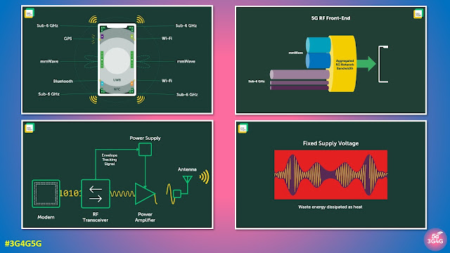
What is RF Front-End (RFFE) and why is it so Important?

As more technologies, frequency bands, antennas, etc., are crammed in our smartphones and tablets, it becomes essential for these devices to keep performing despite what technologies and spectrum are in use at any instant of time. This requires specialist design of the RF front end in our devices. Wikipedia explains it as:

In a radio receiver circuit, the RF front end, short for radio frequency front end, is a generic term for all the circuitry between a receiver's antenna input up to and including the mixer stage. It consists of all the components in the receiver that process the signal at the original incoming radio frequency (RF), before it is converted to a lower intermediate frequency (IF). In microwave and satellite receivers it is often called the low-noise block downconverter (LNB) and is often located at the antenna, so that the signal from the antenna can be transferred to the rest of the receiver at the more easily handled intermediate frequency.

Qualcomm is very active in this area as can be seen from the chart in the Tweet above. Back in October, Qualcomm announced ultraBAW, their new generation of micro acoustic filter technology that expands their RF front-end (RFFE) portfolio and opens up new 5G services and applications. They have a short intro video explaining RFFE:

It is also interesting to see from the Tweet above that on an average baseband + RFFE + connectivity chips cost Apple nearly $55 per device.

The analyst firm CCS Insight have also done some good work explaining RFFE and their analyst Wayne Lam has written a few detailed articles on this topic. Here are the links if you want to read further:

  • Advances in RF Front-Ends Made 5G Phones Possible (link)
  • Advances in 5G RF Front-Ends Lead to Longer Battery Life (link)

Their RFFE videos playlist is embedded below.

Also worth noting that a good modem and RF front-end, especially with 5G, can make a lot of difference in what speeds and coverage you can get

Related Posts:

Monday, November 23, 2020

Radio Design Webinar: Optimising Your 700 MHz Deployments


Radio Design, the award-winning market leader in the provision of wireless infrastructure sharing solutions and RF filter systems, hosted a webinar last week focused on the deployment of the 700 MHz frequency band. This new 700 MHz spectrum is in great demand across the world, mainly due to its long anticipated use as low band 5G spectrum. The webinar explores the potential of this band, as well as how to prepare for potential challenges when deploying.

For people who are familiar with our trainings, we divide the spectrum into three layers, the coverage layer, the capacity layer and the high-throughput layer. 700 MHz is the most popular coverage layer spectrum worldwide.

The slide above from the webinar talks of the recent Austrian 5G Spectrum auction that we blogged about. See tweet below for details

In the webinar, slides and video embedded below, Radio Design’s founder – Eric Hawthorn – kicks things off by analysing the benefits of deploying the 700 MHz band in the real world, before passing over to Global Engineering Director – Steve Shaw – who explores some of the technical problems which can arise, as well as some of the solutions. Last but not least, COO and co-owner of Keima – Iris Barcia – provides her insight into the benefits of deploying the 700 MHz band.

Related Posts:

Tuesday, November 19, 2019

Cell-free Massive MIMO and Radio Stripes


I wrote about "Distributed Massive MIMO using Ericsson Radio Stripes" after MWC 2019 here. I found it a very interesting concept and it will certainly take a few years before it becomes a reality.

Emil Björnson, Associate Professor at Linköping University have produced couple of videos on this topic. I am embedding both of them below for anyone who may be interested.

"A New Look at Cell-Free Massive MIMO" - based on technical paper from PIMRC 2019 on how to design Cell-free Massive MIMO systems that are both scalable and achieve high performance.


Worth noting the following about this video (based on video comments):
  • There are some minor issues with the sudio
  • Cell-free Massive MIMO is particularly for stadiums, streets, and places with many users or where it is hard to provide sufficient network quality with other methods.
  • This concept is still 4-5 years away from being ready to be practically deployed. It should be ready for later part of 5G, probably 5.5G

"Reinventing the Wireless Network Architecture Towards 6G: Cell-free Massive MIMO and Radio Stripes" looks at the motivation behind Cell-free Massive MIMO and how it can be implemented in 6G using radio stripes.


Worth noting the following on this video (based on video comments):

  • It may be possible that multiple frequency bands can be handled in the same radio stripe. If it is found to be possible then every other antenna  processing unit could manage a different band.
  • In principle, you can make the stripe as long as you need. But you probably need to divide it into segments since the power is supplied from one end of a stripe and it will only reach a limited distance (roughly up to 1 km). There are many implementation ideas and it remains to be seen what works out well in practice.

I am looking forward to see it work as it can solve coverage issues in many tricky scenarios.

Related Posts:

Thursday, May 23, 2019

Presentations on Macro Cells and Millimetre-wave Technology from recent CW (Cambridge Wireless) events


CW (Cambridge Wireless) held a couple of very interesting events from 2 very popular groups.

The first one was on "5G wide area coverage: macro cells – the why and the how". This event looked at the design and optimisation of the macro cell layer and its role within future heterogeneous networks. You can access the presentations for limited time on CW website here.

The presentations available are:
Related posts that may be of interest:


The second one was on "Commercialising millimetre-wave technology". The event reviewed the commercial opportunities at millimetre-wave frequencies, what bands are available and what licensing is needed. You can access the presentations on CW website for limited time here.

The presentations available are:

We recently made a video to educate people outside our industry about non-mmWave 5G. It's embedded below.


Friday, April 12, 2019

Slides from Parallel Wireless Webinar: 5G at #MWC19

I hosted a webinar for Parallel Wireless* yesterday about all the stuff related to 5G at Mobile World Congress 2019. The slides are embedded below and can be downloaded from BrightTalk here. You can also listen to the webinar there.


Related posts:


*Full Disclosure: I work for Parallel Wireless as a Senior Director in Strategic Marketing. This blog is maintained in my personal capacity and expresses my own views, not the views of my employer or anyone else. Anyone who knows me well would know this.

Tuesday, April 9, 2019

Distributed Massive MIMO using Ericsson Radio Stripes


One of the interesting things that caught my attention in MWC 2019 was the Ericsson Radio Stripes.

Emil Björnson explains it nicely in his blog as to how this works.

Distributed MIMO deployments combine the best of two worlds: The beamforming gain and spatial interference suppression capability of conventional Massive MIMO with co-located arrays, and the bigger chance of being physically close to a service antenna that small cells offer. Coherent transmission and reception from a distributed MIMO array is not a new concept but has been given many names over the years, including Distributed Antenna System and Network MIMO. Most recently, in the beyond-5G era, it has been called ubiquitous Cell-free Massive MIMO communications and been refined based on insights and methodology developed through the research into conventional Massive MIMO.

One of the showstoppers for distributed MIMO has always been the high cost of deploying a large number of distributed antennas. Since the antennas need to be phase-synchronized and have access to the same data, a lot of high-capacity cables need to be deployed, particularly if a star topology is used. 
...

For those who cannot attend MWC, further conceptual details can be found in a recent overview paper on Cell-free Massive MIMO. An even more detailed description of radio stripes can be found in Ericsson’s patent application from 2017.


The paper explains the Radio stripe system design and also lists the advantages of such a system:

The radio stripe system facilitates a flexible and cheap cell-free Massive MIMO deployment. Cheapness comes from many aspects: (i) deployment does not require highly qualified personnel. Theoretically, a radio stripe needs only one (plug and play) connection either to the front-haul network or directly to the CPU; (ii) a conventional distributed massive MIMO deployment requires a star topology, i.e., a separate cable between each APs and a CPU, which may be economically infeasible. Conversely, radio stripe installation complexity is unaffected by the number of antenna elements, thanks to its compute-and-forward architecture. Hence, cabling becomes much cheaper; (iii) maintenance costs are cut down as a radio stripe system offers increased robustness and resilience: highly distributed functionality offer limited overall impact on the network when few stripes being defected; (iv) low heat-dissipation makes cooling systems simpler and cheaper. While cellular APs are bulky, radio stripes enable invisible installation in existing construction elements as exemplified in Fig. below. Moreover, a radio stripe deployment may integrate for example temperature sensors, microphones/speakers, or vibration sensors, and provide additional features such as fire alarms, burglar alarms, earthquake warning, indoor positioning, and climate monitoring and control.


According to the Ericsson post:

One of the inventors and researchers behind the concept, Jan Hederén, Strategist at Ericsson 4G5G Development, says: 

"Although a large-scale installation of distributed MIMO can provide excellent performance, it can also become an impractical and costly "spaghetti-monster" of cables in case dedicated cables are used to connect the antenna elements.

To be easy to deploy, we need to connect and integrate the antenna elements inside a single cable. We call this solution the "radio stripe" which is an easy way to create a large scale distributed, serial, and integrated antenna system." Says, also inventors and researcher behind the concept."

This visionary concept is an extension of how to build and enhance the capability of current networks. The Radio Stripe systems offers, so to say, new colors and flavors in how we increase the performance of mobile networks.

The Radio Stripe vision is focused on improvements to the reach and quality of radio connectivity in the access part of the mobile network. It shares all other resources (transport, baseband, management, core) with current mobile solutions.

I am looking forward to reading a lot more about this kind of approach in the future and probably some deployment videos too.

Related post:

Friday, September 21, 2018

Base Station Antenna Considerations for 5G

I first mentioned Quintel in this blog three years back for their innovations in 4T8R/8T8R antennas. Since then they have been going strength to strength.


I heard David Barker, CTO of Quintel at Cambridge Wireless event titled "Radio technology for 5G – making it work" talking about the antennas consideration for 5G. There are quite a few important areas in this presentation for consideration. The presentation is embedded below:


Related Posts:

Wednesday, January 24, 2018

Inside AT&T Towers


A really good video from Mr. Mobile on YouTube on how the cell towers look from inside. Worth your 9:27 mins.


If you found this interesting then you will also like:

Tuesday, August 15, 2017

AT&T Blog: "Providing Connectivity from Inside a Cactus"


A recent AT&T blog post looks at how the fake cactus antennas are manufactured. I also took a closeup of a fake cactus antenna when I went to a Cambridge Wireless Heritage SIG event as can be seen in tweet below.

The blog says:
To make a stealth site look as real as possible, our teams use several layers of putty and paint. Our goal is to get the texture and color just right, but also ensure it can withstand natural elements – from snowy Colorado to blistering Arizona. 
Tower production takes 6-8 weeks and starts with constructing a particular mold. The molds quickly become 30-foot tall saguaro cacti or 80-foot tall redwood trees.But these aren’t just steel giants. 
The materials that cover the stealth antennas, like paint or faux-leaves, must be radio frequency-friendly. Stealth antennas designed to look like church steeples or water towers are mostly made of fiberglass. This lets the signal from the antennas penetrate through the casing. 
These stealth deployments are just one of the many unique ways we provide coverage to our customers. So take a look outside, your connection may be closer than you think—hidden in plain sight!
This videos gives a good idea


If this is a topic of interest, then have a look at this collection of around 100 antennas:


See also:


Thursday, July 13, 2017

Different types of Mobile Masts


Today's post is inspired by two things. One of them being my most popular answer on Quora. As you can see, its gathered over 19K upvotes.


The other being #EEGoldenSIM competition started by Marc Allera, CEO of UK mobile operator, EE,. The users were required to find a mast, take a picture and share it. This led to a lot of people asking how do masts look like but also generated lots of interesting pictures. You can search #EEGoldenSIM on twitter to see them.

Below is a presentation prepared by my 3G4G colleagues on how different types of antennas and mobile masts look like. Hope you like it.


Sunday, October 16, 2016

Inside 3GPP Release-13 - Whitepaper by 5G Americas


The following is from the 5G Americas press release:

The summary offers insight to the future of wireless broadband and how new requirements and technological goals will be achieved. The report updates Release 13 (Rel-13) features that are now completed at 3GPP and were not available at the time of the publication of a detailed 5G Americas report, Mobile Broadband Evolution Towards 5G: 3GPP Release 12 & Release 13 and Beyond in June 2015.
The 3GPP standards have many innovations remaining for LTE to create a foundation for 5G.  Rel-12, which was finalized in December 2014, contains a vast array of features for both LTE and HSPA+ that bring greater efficiency for networks and devices, as well as enable new applications and services. Many of the Rel-12 features were extended into Rel-13.  Rel-13, functionally frozen in December 2015 and completed in March 2016, continues to build on these technical capabilities while adding many robust new features.
Jim Seymour, Principal Engineer, Mobility CTO Group, Cisco and co-leader of the 5G Americas report explained, “3GPP Release 13 is just a peek behind the curtain for the unveiling of future innovations for LTE that will parallel the technical work at 3GPP on 5G. Both LTE and 5G will work together to form our connected future.”
The numerous features in the Rel-13 standards include the following for LTE-Advanced:
  • Active Antenna Systems (AAS), including beamforming, Multi-Input Multi-Output (MIMO) and Self-Organizing Network (SON) aspects
  • Enhanced signaling to support inter-site Coordinated Multi-Point Transmission and Reception (CoMP)
  • Carrier Aggregation (CA) enhancements to support up to 32 component carriers
  • Dual Connectivity (DC) enhancements to better support multi-vendor deployments with improved traffic steering
  • Improvements in Radio Access Network (RAN) sharing
  • Enhancements to Machine Type Communication (MTC)
  • Enhanced Proximity Services (ProSe)
Some of the standards work in Rel-13 related to spectrum efficiency include:                                                                                                                       
  • Licensed Assisted Access for LTE (LAA) in which LTE can be deployed in unlicensed spectrum
  • LTE Wireless Local Area Network (WLAN) Aggregation (LWA) where Wi-Fi can now be supported by a radio bearer and aggregated with an LTE radio bearer
  • Narrowband IoT (NB-IoT) where lower power wider coverage LTE carriers have been designed to support IoT applications
  • Downlink (DL) Multi-User Superposition Transmission (MUST) which is a new concept for transmitting more than one data layer to multiple users without time, frequency or spatial separation
“The vision for 5G is being clarified in each step of the 3GPP standards. To understand those steps, 5G Americas provides reports on the developments in this succinct, understandable format,” said Vicki Livingston, Head of Communications for the association.

The whitepaper as follows:


Related posts:

Monday, August 1, 2016

Antenna evolution: From 4G to 5G


I came across this simple Introduction to Antenna Design videos that many will find useful (including myself) for the basics of Antenna. Its embedded below:


In the recently concluded 5G World 2016, Maximilian Göttl, Senior Director, Research & Development, Mobile Communication Systems, Kathrein gave an interesting presentation on Antenna Evolution, from 4G to 5G. The presentation is embedded below.

Please share your thoughts in this area in the comments section below.


Sunday, February 7, 2016

The Art of Disguising Cellular Antennas

When I did a blog post 'Disguising Small Cells in Rural areas' last year, many people were surprised to see these things. So here is another post showing how the antennas looks like and how they have to be disguised to blend in with the environment.


The above pictures shows fake date trees (with dates) near Koutoubia mosque, Marrakech, designed to blend in with the surroundings. In fact I have been told that these fake date trees are common in the Middle East and North African countries.


The above picture is from Dubai, showing similar palm tree. Source unknown.


The above picture, courtesy of Andy Sutton on Twitter shows a cell site near Blandford Forum. I hope you can spot the fake tree on top right.


Another one, courtesy of Andy Sutton on Twitter shows a cell site between motorway M56, J10 & 11 in Cheshire. Single operator but could be shared, single frequency band, x-pole with 3 cell sectors. Only two of the possible 3 cell sectors connected here. Pointing up and down motorway hence 4 feeders.


Another one courtesy of Andy Sutton on Twitter. Its been disguised to not look out of place unless someone is observing very carefully.
All three are fake trees and each is a separate cellular installation. The location is Lancashire, off the A6 between Slyne and Bolton-le-Sands. They are all different operators, left to right, O2, T-Mobile, Orange - although two will become one as part of EE of course.


Modern Art and Cellular Antenna, courtesy of Andy Sutton on Twitter.

What will happen when we transition to 5G, where we will have a lot more antennas because of MIMO (massive or not). China Mobile is researching into Smart Tiles, which are antennas that can be hidden inside Chinese characters. See the following for example:

With more antennas becoming commonplace in the urban environment, operators and vendors will have to keep up coming with innovative ways to disguise the antennas and hope no one notices.

See Also: