At the CW TEC 2025 conference hosted by Cambridge Wireless, veteran wireless engineer Moray Rumney delivered a presentation that challenged the direction the mobile industry has taken. With decades of experience and a sharp eye for what matters, he highlighted a growing and largely ignored problem: the steady decline in the efficiency of antennas in mobile devices.
The evolution of mobile technology has delivered remarkable achievements. From the early days of GSM to the promises of 5G and the ambition of 6G, the industry has continually pushed for higher speeds, more features and greater spectral efficiency. Yet along the way, something essential has been lost. While much of the focus has been on network-side innovation and baseband complexity, the performance of the user device antenna has deteriorated to the point where it is now undermining the potential benefits of these advancements.

According to Moray, antenna performance in smartphones has declined by around 15 decibels since the transition from external antennas in 2G to today’s smartphones. That level of loss has a profound impact. A poor antenna reduces both transmitted and received signal strength. On the uplink side, this means users need to push more power to the network, which drains battery life faster. On the downlink, it forces the network to compensate with stronger transmissions, increasing inter-cell interference and lowering cell-edge throughput. Ultimately, this undermines the overall efficiency and quality of mobile networks. Cell edge performance and indoor coverage is much degraded.
The root of the problem lies in modern smartphone design priorities. Over the years, devices have become slimmer, more stylish and packed with more features. In this pursuit of sleekness, antennas have been compromised. External antennas gave way to internal ones, squeezed into tight spaces surrounded by metal and glass. The visual appeal of the phone has taken precedence over its radio performance. On a technical level, the explosion in the number of supported bands and the increased use of multi-antenna transceivers optimized for high performance in excellent conditions, has reduced the available space for each antenna, reducing the antenna gain accordingly.
This issue was particularly pronounced during the LTE era, where the standards bodies failed to define any radiated performance requirements. Handset performance is based on conducted power, which can appear satisfactory in laboratory conditions. However, once the signal passes through the device's real antenna, the result is often a significant loss. Real-world radiated performance does not match lab conducted measurements.
One of Moray's more memorable illustrations compared the situation to a tube of toothpaste. The conducted performance, which all devices meet, is like a full tube of toothpaste, but with years passing before radiated requirements were finally defined for a few bands in 5G, products with inferior radiated performance were released to the market, which put downward pressure on the radiated requirements that were finally agreed – like squeezing out all the toothpaste. What is left today is a small residue of what used to be. Once compromised, it is extremely difficult to reverse this trend.
He also pointed out a structural problem in how mobile standards are developed. The focus is disproportionately placed on baseband processing and theoretical possibilities, rather than on end-user experience and what actually gets deployed. As new generations arrive, more complexity is added, yet basic aspects like antenna efficiency are overlooked. Testing practices further entrench the problem, as the use of a 50-ohm connector during lab testing limits the scope for real antenna improvements, preventing designers from achieving optimal matching and performance.
Despite all the talk of 6G and beyond, the reality on the ground is less impressive. The UK currently ranks 59th in global mobile speed tests. This is not because of a lack of advanced standards or spectrum, but because of poor deployment decisions and device-related issues like inefficient antennas. It is not a technology gap but a failure to focus on basics that truly matter to users.

Moray argued that significant progress could be made without waiting for 6G. Regulatory bodies could introduce minimum standards for antenna performance, as was once attempted in Denmark. Device certification could include antenna efficiency ratings, encouraging manufacturers to prioritise performance. Networks could enforce stricter indoor coverage targets, and pricing models could be rethought to reduce the strain caused by low-value, high-volume traffic.
He also called attention to battery life, another casualty of inefficient antennas and poor design decisions. Users now routinely carry power banks to get through the day. This is hardly a sign of progress, especially considering the environmental impact of producing and charging these extra devices.
In conclusion, while the industry continues to chase ambitious visions for future generations of mobile technology, there is an urgent need to fix the basics. Antennas are not an exciting topic, but they are fundamental. Without efficient antennas, all the investment in infrastructure, spectrum and software optimisation is wasted. It is time for the industry to refocus, reassess and revalue the importance of the one component every user relies on, but rarely sees.
It really is time to make antennas great again.
Moray’s presentation is embedded below and is available to download from here.
Related Posts:
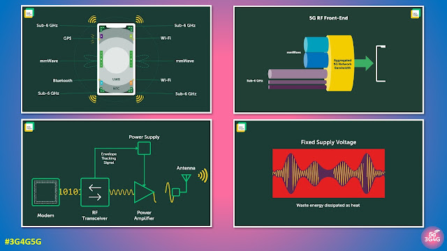
- The 3G4G Blog: What is RF Front-End (RFFE) and why is it so Important?