Showing posts with label Release 18. Show all posts

Tuesday, September 1, 2026

Energy Efficiency Improvements in 3GPP Technologies: From LTE to 5G-Advanced

Energy efficiency has become one of the most important topics in mobile networks. Operators need to support growing traffic, wider bandwidths, massive MIMO, better coverage and new services, while also reducing energy consumption, managing cost and meeting sustainability targets.

We have put together a five-part video series looking at Energy Efficiency Improvements in 3GPP Technologies, starting with LTE and then moving through 5G NR, 5G-Advanced Release 18 and 3GPP Release 19.

The aim of the series is to explain the topic in a structured way. Energy saving in mobile networks is not simply about switching equipment off. It requires careful coordination between radio design, traffic load, user experience, QoS, mobility, device behaviour, RAN hardware, network policies and service requirements.

The five videos in the playlist are:

  1. Energy Efficiency in Mobile Networks: The Basics - This introductory video explains why energy efficiency matters, why the RAN gets most attention, how energy saving differs from energy efficiency, and why measurements and KPIs are essential before optimisation.
  2. How LTE Networks Save Energy - This video looks at LTE energy-saving mechanisms including dormant mode, carrier switch-off, secondary antenna deactivation, common channel power control, Cell DTX, compensation cells, and OAM or signalling-based control.
  3. Why 5G NR Is More Energy Efficient by Design - This part explains the energy-efficiency improvements built into 5G NR, including lean carrier design, sleep opportunities, Bandwidth Parts, carrier aggregation, UE DRX, massive MIMO, beamforming and radio hardware evolution.
  4. 5G-Advanced Release 18 Network Energy Saving - This video looks at Release 18 Network Energy Saving features such as SSB-less SCells, Cell DTX/DRX, CSI enhancements, antenna adaptation, PDSCH power adaptation, Conditional Handover for NES cells and legacy UE handling.
  5. 3GPP Release 19 Energy Efficiency and Energy Saving - The final video looks at Release 19 enhancements including on-demand SSB operation for SCells, on-demand SIB1 for idle/inactive UEs, SSB periodicity adaptation, PRACH and paging adaptation, LP-WUS/WUR, Energy Information Function, OAM, slicing, charging and energy efficiency as a service criterion.

The overall message from the series is that mobile network energy efficiency has evolved from relatively simple resource switch-off mechanisms towards more intelligent, adaptive and service-aware optimisation. LTE introduced many of the early practical ideas. 5G NR provided a more flexible and energy-efficient foundation. 5G-Advanced Release 18 made RAN Network Energy Saving more explicit, and Release 19 expands the topic towards on-demand signalling, UE wake-up efficiency and system-wide energy awareness.

The complete playlist is embedded below.

The main references used for this series include 3GPP article3GPP TR 21.919, 3GPP TR 38.864, 3GPP TR 38.869, NGMN material on 5G energy efficiency best practices, and technical material from Nokia Bell Labs on 5G-Advanced Network Energy Saving.

Related Posts

Friday, August 21, 2026

Multi-Panel UE (MPUE) in 5G and 5G-Advanced

With the introduction of millimetre-wave spectrum in 5G NR, antenna design at the UE became significantly more complicated. At these higher frequencies, increased propagation and penetration losses mean that directional antenna arrays and beamforming are important not only at the base station but also at the device. A single directional antenna array on a smartphone, however, would provide good performance over only part of the surrounding space. Rotate the device, change the direction of the serving cell, or block the antenna with a hand, and the radio link could deteriorate rapidly.

One solution is to place several antenna panels around different parts of the device. This gives rise to the concept of the Multi-Panel User Equipment, or MPUE.

A useful definition appears in a patent on cell reselection for MPUEs. It describes a mobile UE using two or more differently oriented antenna panels, with each providing different angular coverage. Each panel can itself contain multiple closely spaced antenna elements forming an antenna array or antenna module.

In its simplest form, imagine three directional antenna panels positioned around different edges of a smartphone.

Depending on the orientation of the phone, location of the base station and blockage from the user's hand or body, one antenna panel may provide a significantly better radio path than the others.

This type of architecture is particularly interesting for 5G FR2, where directional antenna gain helps compensate for higher path and diffraction losses. Research into MPUE mobility has considered devices with several spatially distinct antenna panels, allowing the UE to exploit antenna directivity while potentially reducing interference arriving from other directions.

An important point is that MPUE should not be thought of simply as a separate type of UE defined by 3GPP.

The antenna-panel implementation has traditionally been largely hidden from the network. In Release 16, for example, antenna panel selection, activation, deactivation and switching were largely left to the UE implementation. Different MPUE hardware architectures can consequently have quite different capabilities and power-consumption characteristics.

Three MPUE assumptions have commonly been used in 3GPP-related work to represent these different hardware capabilities.

  • MPUE-Assumption 1 (MPUE-A1): multiple panels are present, but only one panel can be active at a time. Switching between panels therefore introduces some activation or switching delay.
  • MPUE-Assumption 2 (MPUE-A2): multiple panels can be active simultaneously, and one or more panels can be used for transmission.
  • MPUE-Assumption 3 (MPUE-A3): multiple panels can be active simultaneously for reception and measurements, but only one panel is used for transmission.

These assumptions are useful because having several physical antenna panels does not automatically mean that all of them can measure, receive or transmit simultaneously. The result depends on the RF and baseband architecture inside the device.

This leads to an interesting problem for mobility. If a UE has several antenna panels pointing in different directions, which panel should be used to measure the serving and neighbouring cells?

Research from Nokia and the Vodafone Chair at TU Dresden has looked at this question in multi-beam FR2 networks, particularly comparing MPUE-A1 and MPUE-A3.

With MPUE-A1, only one panel makes measurements at a time. Measurements are therefore effectively obtained sequentially as the UE moves between its available antenna panels.

With MPUE-A3, multiple panels can make measurements simultaneously.

The difference sounds subtle, but it can have an important impact on mobility. Consider a three-panel UE moving through a network. Under MPUE-A3, measurements obtained through all three panels can remain relatively current.

Under MPUE-A1, while Panel 1 is measuring the radio environment, measurements previously obtained through Panels 2 and 3 are getting older. By the time one of those panels is used again, the UE may have moved and the surrounding radio conditions may have changed.

A handover decision can therefore potentially be based on outdated measurements.

The 2022 study Analysis and Performance Evaluation of Mobility for Multi-Panel User Equipment in 5G Networks found that the two MPUE schemes could provide significant mobility-performance gains compared with the reference traditional UE architecture used in the study. It also found that the different MPUE architectures required different mobility-parameter settings to achieve their best performance.

This is an important observation because simply adding more antenna panels does not automatically solve mobility problems. The network procedures and mobility parameters have to take account of how the particular UE actually performs its measurements.

The issue becomes even more interesting when UE-side receive beamforming is added.

Instead of merely selecting one directional antenna panel, the UE can potentially form or steer receive beams within the angular coverage of a panel.

A later study investigated three different UE-side receive-beamforming approaches for an MPUE equipped with three directional panels in a multi-beam FR2 network. In the system-level simulations used in the study, the proposed techniques reduced radio link failures by up to 53% and handover failures by up to 90%. These figures are specific to the assumptions and scenarios used in that research, but they illustrate the potential mobility benefits of combining multiple panels with UE-side beamforming.

There are also interesting implications for interference.

If the serving cell is received strongly through one UE panel while an interfering neighbouring cell lies in a substantially different direction, the directional response of the selected antenna panel can provide some spatial isolation between them.

Research into Fast Conditional Handover has similarly noted that if an MPUE can communicate using panels oriented towards its serving cell, inter-cell interference from neighbouring cells may be significantly suppressed.

A patent from Nokia takes this idea in another direction by proposing the use of spatial separation when performing cell reselection in a network supporting network slicing.

The proposed mechanism considers candidate cells and performs communication-quality measurements using one or more of the UE's antenna panels. It can then consider whether a candidate cell supporting a required network slice is sufficiently spatially separated, or orthogonal, from other candidate cells before selecting it.

It is important to stress that this is a patent proposal rather than functionality defined by current 3GPP cell-reselection procedures.

Cell reselection normally applies when the UE is in RRC_IDLE or RRC_INACTIVE, whereas most of the MPUE mobility research discussed above focuses on connected-mode handover. The patent is interesting precisely because it proposes extending the usefulness of directional MPUE measurements into the cell-reselection problem, particularly where slice availability and intra-frequency interference need to be considered.

The underlying point remains the same: for an MPUE, the radio environment seen by the device can depend not only on where the UE is located, but also on which antenna panel is observing the network and in which direction that panel is looking.

5G-Advanced takes the multi-panel concept another important step forward.

As part of the Release 18 MIMO enhancements, 3GPP introduced support for Simultaneous Transmission with Multi-Panel, or STxMP, for multi-TRP uplink operation.

This allows a capable UE to transmit simultaneously using different antenna panels towards two Transmission/Reception Points, or TRPs.

There are several possibilities.

For single-DCI STxMP Spatial Division Multiplexing (SDM) PUSCH transmission, different spatial layers of one PUSCH are separately transmitted towards the two TRPs.

For single-DCI STxMP Single Frequency Network (SFN) PUSCH transmission, the same layers of one PUSCH are transmitted towards the two TRPs. This provides transmission diversity and can improve robustness.

For multi-DCI STxMP PUSCH+PUSCH transmission, two PUSCH transmissions are transmitted towards the two TRPs.

This distinction is worth making carefully. Separate PUSCH transmissions belong to the multi-DCI PUSCH+PUSCH case; the single-DCI SDM case divides different layers of one PUSCH between the two TRPs.

Release 18 therefore represents an interesting evolution of the MPUE concept.

Initially, multiple antenna panels were largely about giving a highly directional UE better angular coverage and allowing it to select an appropriate panel as its orientation and radio environment changed.

The evolution can roughly be thought of as:

Multiple antenna panels
→ Broader angular coverage
→ Panel selection and switching
→ Panel-aware measurements
→ UE-side beamforming
→ Improved mobility and spatial interference isolation
→ Simultaneous multi-panel transmission

There are, of course, trade-offs.

Supporting several simultaneously active antenna panels may require additional RF chains and baseband processing, increasing hardware complexity and power consumption. MPUE-A1 avoids some of this complexity by using one panel at a time, but sequential measurements can become outdated and panel switching can introduce delay.

More capable architectures can provide fresher measurements and support simultaneous panel operation, but potentially at a higher implementation and energy cost.

The network and UE therefore need to balance radio performance, mobility robustness, measurement freshness, hardware capability and power consumption.

MPUE is consequently much more interesting than simply saying that a 5G smartphone contains several antenna arrays.

At FR2 in particular, the physical orientation and capabilities of those antenna panels can influence how the UE sees the network, how reliably it moves between cells and how effectively it exploits directional beamforming.

With 5G-Advanced Release 18 STxMP, multiple UE panels can now also become part of the simultaneous uplink transmission strategy towards multiple TRPs.

As mobile networks make greater use of beamforming, multi-TRP operation and increasingly sophisticated MIMO techniques, understanding the antennas and RF capabilities inside the UE becomes an increasingly important part of understanding how the overall radio network performs.

Related Posts

Thursday, October 9, 2025

Seamless UE Context Recovery (SUECR) in 3GPP Release 18

3GPP Release 18 introduces a wide range of enhancements across the 5G system, from energy efficiency and XR optimisation to AI-powered features. Among these developments is a practical but important addition known as Seamless User Equipment Context Recovery (SUECR), designed to handle situations where a device temporarily goes offline.

When a device such as a smartphone or IoT unit undergoes an operating system upgrade, a modem reset or a software update, it may become unavailable for a period of time. If this happens without informing the network, the operator’s core functions and connected application servers may continue to treat the device as available. This can result in wasted signalling, unnecessary retries and disruptions to critical operations that depend on the device’s availability.

SUECR provides a solution by allowing the device to notify the network of an unavailability period, which is a defined window of time during which it cannot communicate. Both the device and the core network retain important session and mobility information so that once the device returns, service can continue smoothly without unnecessary procedures.

The feature works in two ways depending on the device’s ability to store context information. If the device can preserve its mobility and session management contexts in non-volatile memory or on the SIM, it executes a registration procedure before going offline. The unavailability period is included in this request, and the Access and Mobility Management Function (AMF) records the duration and recognises the device as unreachable until it re-registers. If an application function has subscribed to receive updates on device availability, the AMF also forwards this information so that application servers can adapt accordingly. If the device cannot save its context, it instead executes a deregistration procedure to notify the AMF of its unavailability, with similar treatment by the network until the device performs its next registration.

Once the update or reset is complete, the device re-registers with the network and resumes normal service. If the planned downtime is delayed, cancelled or extended, the device repeats the procedure to keep the network and applications accurately informed. This ensures that network functions and application servers no longer waste resources attempting to reach devices that are temporarily offline.

By introducing SUECR, Release 18 strengthens service reliability and efficiency. It prevents unnecessary signalling and enables critical applications to maintain accurate awareness of device availability. The figure above, from NTT Docomo’s Technical Journal, illustrates how the unavailability period is managed depending on whether the registration or deregistration procedure is used.

Seamless User Equipment Context Recovery may appear as a small enhancement in the context of all the new Rel-18 features, but it addresses an important gap in 5G operations. As networks continue to evolve towards automation and support for mission-critical services, this function will play a key role in making device management more predictable and dependable.

Related Posts

Thursday, August 21, 2025

Understanding L1/L2 Triggered Mobility (LTM) Procedure in 3GPP Release 18

In an earlier post we looked at the 3GPP Release 18 Description and Summary of Work Items. One of the key areas was Further NR mobility enhancements, where a new feature called L1/L2-triggered mobility (LTM) has been introduced. This procedure aims to reduce mobility latency and improve handover performance in 5G-Advanced.

Mobility has always been one of the most important areas in cellular networks. The ability of a user equipment (UE) to move between cells without losing service is essential for reliability and performance. Traditional handover procedures in 4G and 5G rely on Layer 3 (L3) signalling, which is robust but can result in high signalling overhead and connection interruption times of 50 to 90 milliseconds. While most consumer services can tolerate this, advanced use cases with strict latency demands cannot.

3GPP Release 18 takes a significant step forward by introducing the L1/L2 Triggered Mobility (LTM) procedure. Instead of relying only on L3 signalling, LTM shifts much of the handover process down to Layer 1 (physical) and Layer 2 (MAC), making it both faster and more efficient. The goal is to reduce interruption to around 20 to 30 milliseconds, a level that can better support applications in ultra-reliable low latency communication, extended reality and mobility automation.

The principle behind LTM is straightforward. The UE is preconfigured with candidate target cells by the network. These configurations can be provided in two ways: either as a common reference with small delta updates for each candidate or as complete configurations. Keeping the configuration of multiple candidates allows the UE to switch more quickly without requiring another round of reconfiguration after each move.

Measurements are then performed at lower layers. The UE reports reference signal measurements and time and phase information to the network. Medium Access Control (MAC) control elements are used to activate or deactivate target cell states, including transmission configuration indicator (TCI) states. This ensures the UE is already aware of beam directions and reference signals in the target cells before the actual switch.

A particularly important innovation in LTM is the concept of pre-synchronisation. Both downlink and uplink pre-synchronisation can take place while the UE is still connected to the serving cell. For downlink, the network instructs the UE to align with a candidate cell’s beams. For uplink, the UE can transmit a random-access preamble towards a target cell, and the network calculates a timing advance (TA) value. This TA is stored and delivered only at the moment of execution, allowing the UE to avoid a new random access procedure. In cases where TA is already known or equal to the serving cell, the handover becomes RACH-less, eliminating a significant source of delay.

The final step is the LTM cell switch command. This MAC control element carries the chosen target configuration, TA value and TCI state indication. Since synchronisation has already been achieved, the UE can break the old connection and resume data transfer almost immediately in the new cell.

Compared to earlier attempts such as Dual Active Protocol Stack (DAPS) handover, which required maintaining two simultaneous connections and faced practical limitations, LTM offers a more scalable solution. It can be applied across frequency ranges, including higher bands above 7 GHz where beamforming is critical, and it works for both intra-DU and inter-DU mobility within a gNB.

The Release 18 specification restricts LTM to intra-gNB mobility, but work has already begun in Release 19 to expand it further. Future enhancements are expected to cover inter-gNB mobility and to refine measurement reporting for even greater efficiency.

Looking beyond 5G Advanced, new concepts are being explored for 6G. At the Brooklyn 6G Summit 2024, MediaTek introduced the idea of L1/L2 Triggered Predictive Mobility (LTPM), where predictive intelligence could play a role in mobility decisions. While this is still at an early research stage, it points to how mobility management will continue to evolve.

For now, the introduction of LTM marks a practical and important milestone. By reducing handover latency significantly, it brings the network closer to meeting the demanding requirements of next generation services while maintaining efficiency in signalling and resource use.

Related Posts

Thursday, May 8, 2025

3GPP Release 18 Signal level Enhanced Network Selection (SENSE) for Smarter Network Selection in Stationary IoT

As 5G evolves and the number of deployed IoT devices increases globally, efficient and reliable network selection becomes ever more critical. Particularly for stationary devices deployed in remote, deep-indoor or roaming environments, traditional selection mechanisms have struggled to provide robust connectivity. This has led to operational challenges, especially for use cases involving low-power or hard-to-reach sensors. In response, 3GPP Release 18 introduces a new capability under the SA2 architecture work, Signal level Enhanced Network Selection (SENSE), designed to tackle this exact issue.

In today’s cellular systems, when a User Equipment (UE), including IoT modules, switches on or recovers from a loss of coverage, it performs automatic network selection. This typically prioritises networks based on preferences such as PLMN priority lists and broadcast cell selection criteria, while largely ignoring the actual signal strength at the device’s location. This approach works reasonably well for mobile consumer devices that can adapt through user movement or manual intervention. However, for stationary IoT UEs, which are often unmanned and deployed permanently in locations with limited or fluctuating radio conditions, this method can result in persistent suboptimal connectivity.

The issue becomes most evident when a device latches onto a visited PLMN (VPLMN) with higher priority despite poor signal quality. The UE might remain connected to this weak network, struggling to maintain bearer sessions or repeatedly failing data transfers. These failures often go undetected by the operator's monitoring systems and may require expensive manual intervention in the field. The cumulative impact of such maintenance activities adds significantly to operational expenditure, especially in mass-scale IoT deployments.

SENSE aims to fix this problem by making signal level an integral part of the automatic network selection and reselection process. Rather than simply following preconfigured priority rules, UEs enabled with SENSE will now assess the received signal quality during network selection. This allows them to favour networks that offer stronger and more stable radio conditions, even if they have lower priority, when such conditions are essential for reliable connectivity.

The capability is particularly targeted at stationary IoT UEs that support NB-IoT, EC-GSM-IoT, or LTE Cat-M1/M2. These devices are often used in applications such as water level monitoring, power grid sensors, and remote metering, installations where physical access post-deployment may be difficult or even infeasible.

To implement SENSE, the Home PLMN (HPLMN) can configure the UE to apply Operator Controlled Signal Thresholds (OCST) for each supported access technology. These thresholds are stored within the USIM and define the minimum signal quality required for a network to be considered viable. The OCST settings can be provisioned before deployment or updated later via standard NAS signalling mechanisms, including the Steering of Roaming (SoR) feature.

When a SENSE-enabled UE attempts to select a network, it checks whether the signal level from any candidate network meets or exceeds the configured OCST for its supported radio access technologies. If it does, the UE proceeds to register with that PLMN. If no suitable network meets the signal thresholds, the UE falls back to the legacy selection process, which excludes signal strength as a factor. This dual-iteration method ensures backward compatibility while enabling more robust performance where SENSE is supported.

Additionally, SENSE influences periodic network reselection. If the average signal quality from a registered PLMN drops below the OCST threshold over time, the UE will proactively seek alternative PLMNs whose signals meet the configured criteria. This continuous evaluation helps avoid long-term connectivity issues that may otherwise remain unnoticed.

SENSE is not intended to disrupt roaming steering or PLMN preferences altogether. Instead, it introduces a smart, context-aware filter that empowers the UE to make better decisions when radio conditions are poor. By integrating signal level awareness early in the selection logic, operators gain a powerful new tool to reduce failure rates and minimise costly field maintenance.

As the IoT landscape expands across industries and geographies, features like SENSE will play a vital role in supporting dependable, scalable and autonomous deployments. In Release 18, 3GPP has taken a meaningful step towards improving network availability for devices that need to just work, no matter where they are.

Related Posts

Tuesday, November 26, 2024

Low Latency Power Saving with Low Power-Wake Up Signal/Receiver (LP-WUS/LP-WUR)

Power-saving methodologies have been integral to all generations of 3GPP technologies, aimed at reducing the power consumption of user equipment (UEs) and other battery-dependent devices. Some of the stringent requirements of 5G, such as achieving a 10-year battery life for certain IoT devices, have necessitated further optimisation of power consumption. To address this, 3GPP Release 16 introduced the Wake-Up Signal (WUS) power-saving mechanism, designed to significantly reduce energy usage in UEs. For a detailed technical explanation, ShareTechnote provides an excellent overview.

The concept of wake-up radios has been explored for over a decade. In a 2017 blog post, Ericsson highlighted how researchers had been working on designing wake-up radios and receivers, initially aimed at IEEE 802.11 (Wi-Fi) technologies. This idea later gained traction in 3GPP discussions, culminating in a study conducted during Release 18. The findings are comprehensively documented in 3GPP TR 38.869: Study on low-power wake-up signal and receiver for NR (Release 18).

Quoting from the introduction of 3GPP 38.869:

5G systems are designed and developed targeting for both mobile telephony and vertical use cases. Besides latency, reliability, and availability, UE energy efficiency is also critical to 5G. Currently, 5G devices may have to be recharged per week or day, depending on individual's usage time. In general, 5G devices consume tens of milliwatts in RRC idle/inactive state and hundreds of milliwatts in RRC connected state. Designs to prolong battery life is a necessity for improving energy efficiency as well as for better user experience. 

Energy efficiency is even more critical for UEs without a continuous energy source, e.g., UEs using small rechargeable and single coin cell batteries. Among vertical use cases, sensors and actuators are deployed extensively for monitoring, measuring, charging, etc. Generally, their batteries are not rechargeable and expected to last at least few years as described in TR 38.875. Wearables include smart watches, rings, eHealth related devices, and medical monitoring devices. With typical battery capacity, it is challenging to sustain up to 1-2 weeks as required. 

The power consumption depends on the configured length of wake-up periods, e.g., paging cycle. To meet the battery life requirements above, eDRX cycle with large value is expected to be used, resulting in high latency, which is not suitable for such services with requirements of both long battery life and low latency. For example, in fire detection and extinguishment use case, fire shutters shall be closed and fire sprinklers shall be turned on by the actuators within 1 to 2 seconds from the time the fire is detected by sensors, long eDRX cycle cannot meet the delay requirements. eDRX is apparently not suitable for latency-critical use cases. Thus, the intention is to study ultra-low power mechanism that can support low latency in Rel-18, e.g. lower than eDRX latency.

Currently, UEs need to periodically wake up once per DRX cycle, which dominates the power consumption in periods with no signalling or data traffic. If UEs are able to wake up only when they are triggered, e.g., paging, power consumption could be dramatically reduced. This can be achieved by using a wake-up signal to trigger the main radio and a separate receiver which has the ability to monitor wake-up signal with ultra-low power consumption. Main radio works for data transmission and reception, which can be turned off or set to deep sleep unless it is turned on.

The power consumption for monitoring wake-up signal depends on the wake-up signal design and the hardware module of the wake-up receiver used for signal detecting and processing. 

The study should primarily target low-power WUS/WUR for power-sensitive, small form-factor devices including IoT use cases (such as industrial sensors, controllers) and wearables. Other use cases are not precluded, e.g.XR/smart glasses, smart phones. 

As opposed to the work on UE power savings in previous releases, this study will not require existing signals to be used as WUS. All WUS solutions identified shall be able to operate in a cell supporting legacy UEs. Solutions should target substantial gains compared to the existing Rel-15/16/17 UE power saving mechanisms. Other aspects such as detection performance, coverage, UE complexity, should be covered by the evaluation.

Qualcomm's blog post looking at 'How will wireless innovations foster a greener, more sustainable future?' is also worth reading on this topic.

Related Posts

Wednesday, August 14, 2024

3GPP Release 18 Description and Summary of Work Items

The first official release of 3GPP TR 21.918: "Release 18 Description; Summary of Rel-18 Work Items" has been published. It's the first official version of 5G-Advanced. Quoting from the report: 

Release 18 specifies further improvements of the 5G-Avanced system. 

These improvements consist both in enhancements of concepts/Features introduced in the previous Releases and in the introduction of new topics.

Some of the key improvements are:

  • a further integration of the Satellite (NTN) access (introduced in Rel-17) in the 5G System (5GS), 
  • a more efficient support of Internet of Things (IoT), Machine-Type Communication (MTC), including by satellite coverage
  • and also several aspects of proximity communication and location (Sidelink, Proximity, Location and Positioning, better support of the industrial needs (Verticals, Industries, Factories, Northbound API), Multicast and Broadcast Services (MBS), Network Slicing or Uncrewed Aerial Vehicles (UAV).

As for the new topics, some of the key aspects are:

  • Energy Efficiency (EE)
  • Artificial Intelligence (AI)/Machine Learning (ML)
  • eXtended, Augmented and Virtual Reality (XR, AR, VR), immersive communications

The following list is from the v1.0.0 table of contents to make it easier to find the list of topics. If it interests you, download the latest version technical report from the directory here.

5 Satellite / Non-Terrestrial Network (NTN)
5.1 General aspects
5.1.1 User plane: “5G system with satellite backhaul”
5.1.2 Discontinuous coverage: “Satellite access Phase 2”
5.1.3 Radio: "NR NTN enhancements"
5.1.4 Charging and Management aspects of Satelite
5.2 Specific aspects
5.2.1 IoT (Internet of Things) NTN enhancements
5.2.2 Guidelines for Extra-territorial 5G Systems
5.2.3 5G system with satellite access to Support Control and/or Video Surveillance
5.2.4 Introduction of the satellite L-/S-band for NR
5.2.5 Other band-related aspects of satellite

6 Internet of Things (IoT), Machine-Type Communication (MTC)
6.1 Personal IoT and Residential networks
6.2 Enhanced support of Reduced Capability (RedCap) NR devices
6.3 NR RedCap UE with long eDRX for RRC_INACTIVE State
6.4 Application layer support for Personal IoT Network
6.5 5G Timing Resiliency System
6.6 Mobile Terminated-Small Data Transmission (MT-SDT) for NR
6.7 Adding new NR FDD bands for RedCap in Rel-18
6.8 Signal level Enhanced Network Selection
6.9 IoT NTN enhancements

7 Energy Efficiency (EE)
7.1 Enhancements of EE for 5G Phase 2
7.2 Network energy savings for NR
7.3 Smart Energy and Infrastructure

8 Uncrewed Aerial Vehicles (UAV), UAS, UAM
8.1 Architecture for UAV and UAM Phase 2
8.2 Architecture for UAS Applications, Phase 2
8.3 NR support for UAV
8.4 Enhanced LTE Support for UAV

9 Sidelink, Proximity, Location and Positioning
9.1 5GC LoCation Services - Phase 3
9.2 Expanded and improved NR positioning
9.3 NR sidelink evolution
9.4 NR sidelink relay enhancements
9.5 Proximity-based Services in 5GS Phase 2
9.6 Ranging-based Service and sidelink positioning
9.7 Mobile Terminated-Small Data Transmission (MT-SDT) for NR
9.8 5G-enabled fused location service capability exposure

10 Verticals, Industries, Factories, Northbound API
10.1 Low Power High Accuracy Positioning for industrial IoT scenarios
10.2 Application enablement aspects for subscriber-aware northbound API access
10.3 Smart Energy and Infrastructure
10.4 Generic group management, exposure and communication enhancements
10.5 Service Enabler Architecture Layer for Verticals Phase 3
10.6 SEAL data delivery enabler for vertical applications
10.7 Rel-18 Enhancements of 3GPP Northbound and Application Layer interfaces and APIs
10.8 Charging Aspects of B2B
10.9 NRF API enhancements to avoid signalling and storing of redundant data
10.10 GBA_U Based APIs
10.11 Other aspects

11 Artificial Intelligence (AI)/Machine Learning (ML)
11.1 AI/ML model transfer in 5GS
11.2 AI/ML for NG-RAN
11.3 AI/ML management & charging
11.4 NEF Charging enhancement to support AI/ML in 5GS

12 Multicast and Broadcast Services (MBS)
12.1 5G MBS Phase 2
12.2 Enhancements of NR MBS
12.3 UE pre-configuration for 5MBS
12.4 Other MBS aspects

13 Network Slicing
13.1 Network Slicing Phase 3
13.2 Enhancement of NSAC for maximum number of UEs with at least one PDU session/PDN connection
13.3 Enhancement of Network Slicing UICC application for network slice-specific authentication and authorization
13.4 Charging Aspects of Network Slicing Phase 2
13.5 Charging Aspects for NSSAA
13.6 Charging enhancement for Network Slice based wholesale in roaming
13.7 Network Slice Capability Exposure for Application Layer Enablement
13.8 Other slice aspects

14 eXtended, Augmented and Virtual Reality (XR, AR, VR), immersive
14.1 XR (eXtended Reality) enhancements for NR
14.2 Media Capabilities for Augmented Reality
14.3 Real-time Transport Protocol Configurations
14.4 Immersive Audio for Split Rendering Scenarios  (ISAR)
14.5 Immersive Real-time Communication for WebRTC
14.6 IMS-based AR Conversational Services
14.7 Split Rendering Media Service Enabler
14.8 Extended Reality and Media service (XRM)
14.9 Other XR/AR/VR items

15 Mission Critical and emergencies
15.1 Enhanced Mission Critical Push-to-talk architecture phase 4
15.2 Gateway UE function for Mission Critical Communication
15.3 Mission Critical Services over 5MBS
15.4 Mission Critical Services over 5GProSe
15.5 Mission Critical ad hoc group Communications
15.6 Other Mission Critical aspects

16 Transportations (Railways, V2X, aerial)
16.1 MBS support for V2X services
16.2 Air-to-ground network for NR
16.4 Interconnection and Migration Aspects for Railways
16.5 Application layer support for V2X services; Phase 3
16.6 Enhanced NR support for high speed train scenario in frequency range 2 (FR2)

17 User Plane traffic and services
17.1 Enhanced Multiparty RTT
17.2 5G-Advanced media profiles for messaging services
17.3 Charging Aspects of IMS Data Channel
17.4 Evolution of IMS Multimedia Telephony Service
17.5 Access Traffic Steering, Switch and Splitting support in the 5G system architecture; Phase 3
17.6 UPF enhancement for Exposure and SBA
17.7 Tactile and multi-modality communication services
17.8 UE Testing Phase 2
17.9 5G Media Streaming Protocols Phase 2
17.10 EVS Codec Extension for Immersive Voice and Audio Services
17.11 Other User Plane traffic and services items

18 Edge computing
18.1 Edge Computing Phase 2
18.2 Architecture for enabling Edge Applications Phase 2
18.3 Edge Application Standards in 3GPP and alignment with External Organizations

19 Non-Public Networks
19.1 Non-Public Networks Phase 2
19.2 5G Networks Providing Access to Localized Services
19.3 Non-Public Networks Phase 2

20 AM and UE Policy
20.1 5G AM Policy
20.2 Enhancement of 5G UE Policy
20.3 Dynamically Changing AM Policies in the 5GC Phase 2
20.4 Spending Limits for AM and UE Policies in the 5GC
20.5 Rel-18 Enhancements of UE Policy

21 Service-based items
21.1 Enhancements on Service-based support for SMS in 5GC
21.2 Service based management architecture
21.3 Automated certificate management in SBA
21.4 Security Aspects of the 5G Service Based Architecture Phase 2
21.5 Service Based Interface Protocol Improvements Release 18

22 Security-centric aspects
22.1 IETF DTLS protocol profile for AKMA and GBA
22.2 IETF OSCORE protocol profiles for GBA and AKMA
22.3 Home network triggered primary authentication
22.4 AKMA phase 2
22.5 5G Security Assurance Specification (SCAS) for the Policy Control Function (PCF)
22.6 Security aspects on User Consent for 3GPP services Phase 2
22.7 SCAS for split-gNB product classes
22.8 Security Assurance Specification for AKMA Anchor Function Function (AAnF)
22.9 Other security-centric items

23 NR-only items
23.1 Not band-centric
23.1.1 NR network-controlled repeaters
23.1.2 Enhancement of MIMO OTA requirement for NR UEs
23.1.3 NR MIMO evolution for downlink and uplink
23.1.4 Further NR mobility enhancements
23.1.5 In-Device Co-existence (IDC) enhancements for NR and MR-DC
23.1.6 Even Further RRM enhancement for NR and MR-DC
23.1.7 Dual Transmission Reception (TxRx) Multi-SIM for NR
23.1.8 NR support for dedicated spectrum less than 5MHz for FR1
23.1.9 Enhancement of NR Dynamic Spectrum Sharing (DSS)
23.1.10 Multi-carrier enhancements for NR
23.1.11 NR RF requirements enhancement for frequency range 2 (FR2), Phase 3
23.1.12 Requirement for NR frequency range 2 (FR2) multi-Rx chain DL reception
23.1.13 Support of intra-band non-collocated EN-DC/NR-CA deployment
23.1.14 Further enhancements on NR and MR-DC measurement gaps and measurements without gaps
23.1.15 Further RF requirements enhancement for NR and EN-DC in frequency range 1 (FR1)
23.1.16 Other non-band related items
23.2 Band-centric
23.2.1 Enhancements of NR shared spectrum bands
23.2.2 Addition of FDD NR bands using the uplink from n28 and the downlink of n75 and n76
23.2.3 Complete the specification support for BandWidth Part operation without restriction in NR
23.2.4 Other NR band related topics

24 LTE-only items
24.1 High Power UE (Power Class 2) for LTE FDD Band 14
24.2 Other LTE-only items

25 NR and LTE items
25.1 4Rx handheld UE for low NR bands (<1GHz) and/or 3Tx for NR inter-band UL Carrier Aggregation (CA) and EN-DC
25.2 Enhancement of UE TRP and TRS requirements and test methodologies for FR1 (NR SA and EN-DC)
25.3 Other items

26 Network automation
26.1 Enablers for Network Automation for 5G phase 3
26.2 Enhancement of Network Automation Enablers

27 Other aspects
27.1 Support for Wireless and Wireline Convergence Phase 2
27.2 Secondary DN Authentication and authorization in EPC IWK cases
27.3 Mobile IAB (Integrated Access and Backhaul) for NR
27.4 Further NR coverage enhancements
27.5 NR demodulation performance evolution
27.6 NR channel raster enhancement
27.7 BS/UE EMC enhancements for NR and LTE
27.8 Enhancement on NR QoE management and optimizations for diverse services
27.9 Additional NRM features phase 2
27.10 Further enhancement of data collection for SON (Self-Organising Networks)/MDT (Minimization of Drive Tests) in NR and EN-DC
27.11 Self-Configuration of RAN Network Entities
27.12 Enhancement of Shared Data ID and Handling
27.13 Message Service within the 5G system Phase 2
27.14 Security Assurance Specification (SCAS) Phase 2
27.15 Vehicle-Mounted Relays
27.16 SECAM and SCAS for 3GPP virtualized network products
27.17 SECAM and SCAS for 3GPP virtualized network products
27.18 MPS for Supplementary Services
27.19 Rel-18 enhancements of session management policy control
27.20 Seamless UE context recovery
27.21 Extensions to the TSC Framework to support DetNet
27.22 Multiple location report for MT-LR Immediate Location Request for regulatory services
27.23 Enhancement of Application Detection Event Exposure
27.24 General Support of IPv6 Prefix Delegation in 5GS
27.25 5G Timing Resiliency System
27.26 MPS when access to EPC/5GC is WLAN
27.27 Data Integrity in 5GS
27.28 Security Enhancement on RRCResumeRequest Message Protection

28 Administration, Operation, Maintenance and Charging-centric Features
28.1 Introduction
28.2 Intent driven Management Service for Mobile Network phase 2
28.3 Management of cloud-native Virtualized Network Functions
28.4 Management of Trace/MDT phase 2
28.5 Security Assurance Specification for Management Function (MnF)
28.6 5G performance measurements and KPIs phase 3
28.7 Access control for management service
28.8 Management Aspects related to NWDAF
28.9 Management Aspect of 5GLAN
28.10 Charging Aspects of TSN
28.11 CHF Distributed Availability
28.12 Management Data Analytics phase 2
28.12 5G System Enabler for Service Function Chaining
28.13 Other Management-centric items

29 Other Rel-18 Topics

If you find them useful then please get the latest document from here.

Related Posts

Wednesday, January 24, 2024

UE Assistance Information in LTE and 5G

I have been asked about the UE Assistance Information (UAI) RRC message a few times before. Generally I have always pointed people back to the LTE/5G specifications but here is a concise video that the telecoms technology training company Mpirical have shared recently:

If you want to dig further into details then please see the RRC specifications: 36.331 for LTE and 38.331 for 5G. 

Over the years I have added quite a few short tutorials from Mpirical on this blog, do check them out below.

Related Posts

Friday, February 3, 2023

ATIS Webinar on "3GPP Release 18 Overview: A World of 5G-Advanced"

Yesterday, ATIS, one of the seven 3GPP Organizational Partner (OP), delivered on online webinar on 3GPP Release 18 Overview: The World of 5G-Advanced. A summary of the webinar according to ATIS as follows:

As the first release of 5G-Advanced, Release 18 has been progressing well despite the challenges in fully resuming 3GPP face-to-face meetings in 2022.

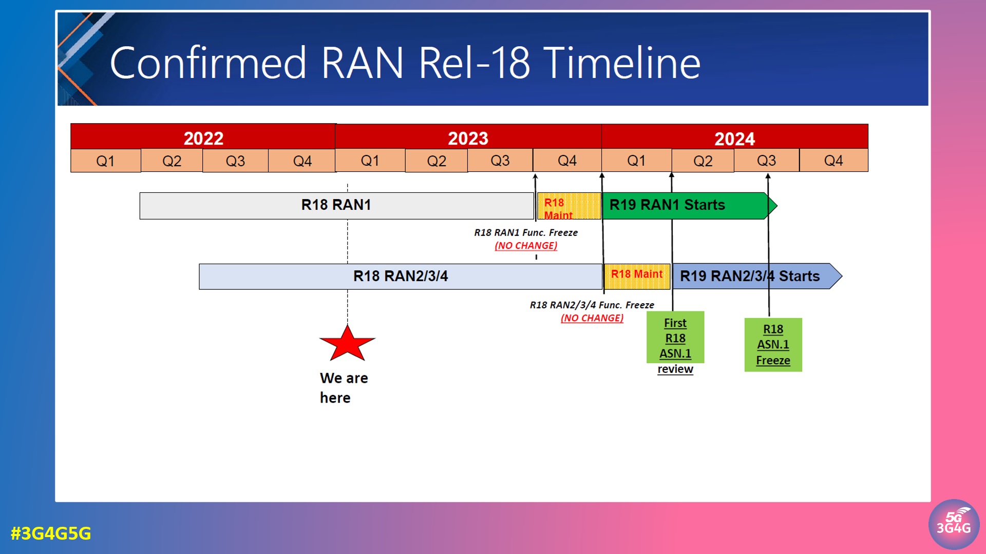
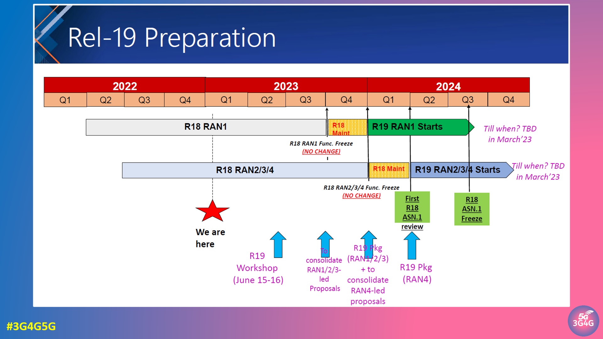
In this webinar, ATIS provides a high-level summary of 3GPP Release 18: the confirmed Rel-18 timeline, status for the ongoing study and work items, and the newly converted work items from the completed study items. We also give a brief introduction of the preparation for Release 19 aiming for approval of the package of projects in December 2023.

Distinguished speakers included:

  • Wanshi Chen (Qualcomm, Chair of 3GPP RAN Plenary) will provide a view on radio interface and RAN system aspects.
  • Puneet Jain (Intel, Chair of 3GPP System Architecture Group – SA2) will look at whole system capabilities and network aspects.
  • Moderator: Iain Sharp, Principal Technologist, ATIS

The recording of the webinar is embedded below and slides available here.

Just a reminder, 5G covers Release 15, 16 and 17. 5G-Advanced is Release-18 onwards. Ideally, 18, 18 and 20. 6G should start with Release 21. Based on the current industry adoption of 5G, there is no reason to push the next generation on the operators before it's mature and everyone is ready to take it onboard.

Related Posts:

Monday, August 22, 2022

DCCA Features and Enhancements in 5G New Radio

In another new whitepaper on 5G-Advanced, Nokia has detailed DCCA (DC + CA) features and enhancements from Rel-15 until Rel-18. The following is an extract from the paper:

Mobility is one of the essential components of 5G-Advanced. 3GPP has already defined a set of functionalities and features that will be a part of the 5G-Advanced Release 18 package. These functionalities can be grouped into four areas: providing new levels of experience, network extension into new areas, mobile network expansion beyond connectivity, and providing operational support excellence. Mobility enhancements in Release 18 will be an important part of the ‘Experience enhancements” block of features, with the goal of reducing interruption time and improving mobility robustness.

Fig. 2 shows a high-level schematic of mobility and dual connectivity (DC)/Carrier Aggregation (CA) related mechanisms that are introduced in the different 5G legacy releases towards 5G-Advanced in Release 18. Innovations such as Conditional Handover (CHO) and dual active protocol stack (DAPS) are introduced in Release 16. More efficient operation of carrier aggregation (CA), dual connectivity (DC), and the combination of those denoted as DCCA, as well as Multi-Radio Access Technology DC (MR-DC) are introduced through Releases 16 and 17.

For harvesting the full benefits of CA/DC techniques, it is important to have an agile framework where secondary cell(s) are timely identified and configured to the UE when needed. This is of importance for non-standalone (NSA) deployments where a carrier on NR should be quickly configured and activated to take advantage of 5G. Similarly, it is of importance for standalone (SA) cases where e.g. a UE with its Primary Cell (PCell) on NR Frequency Range 1 (FR1) wants to take additional carriers, either on FR1 and/or FR2 bands, into use. Thus, there is a need to support cases where the aggregated carriers are either from the same or difference sites. The management of such additional carriers for a UE shall be highly agile in line with the user traffic and QoS demands; quickly enabling usage of additional carriers when needed and again quickly released when no longer demanded to avoid unnecessary processing at the UE and to reduce its energy consumption. This is of particular importance for users with time-varying traffic demands (aka burst traffic conditions).

In the following, we describe how such carrier management is gradually improved by introducing enhancements for cell identification, RRM measurements and reduced reporting delays from UEs. As well as innovations related to Conditional PSCell Addition and Change (CPAC) and deactivation of secondary cell groups are outlined.

The paper goes on to discuss the following scenarios in detail for DCCA enhancements:

  • Early measurement reporting
  • Secondary cell (SCell) activation time improvements
    • Direct SCell activation
    • Temporary RS (TRS)-based SCell Activation
  • Conditional Secondary Node (SN) addition and change for fast access
  • Activation of secondary cell group

The table below summarizes the DCCA features in 5G NR

Related Posts