Showing posts with label 4G. Show all posts

Thursday, October 24, 2024

4G/LTE, 5G and Private Networks in Africa

The Global mobile Suppliers Association (GSA) recently released its "Regional Spotlight Africa – October 2024" report. It tracks 604 public mobile networks across North and Sub-Saharan Africa, including LTE, LTE-Advanced, 5G, and fixed wireless access networks. The report gives an up-to-date view of 4G and 5G deployment in Africa, using the latest data and insights from GSA's various reports on mobile networks and satellite services.

Africa has seen major progress in telecommunications in recent years. The expansion of 4G LTE networks has improved data speeds, enhanced connectivity, and supported the spread of mobile broadband services. Looking ahead, 5G technology promises even faster speeds, lower latency, and stronger security, opening the door to new possibilities in connectivity.

The report covers key areas of mobile network development, such as:

  • The current state of LTE and 5G rollouts
  • LTE-Advanced advancements
  • 5G standalone networks
  • The growth of private networks
  • Phasing out 2G and 3G technologies
  • Progress in satellite services

Alongside the report, GSA hosted a regional webinar where the research team shared insights on:

  • The status of LTE and LTE-Advanced in Africa and how it compares globally
  • Whether 5G development is being delayed by ongoing LTE rollouts and older devices
  • Recent spectrum auctions and assignments
  • The transition from 2G and 3G networks
  • The potential for satellite non-terrestrial (NTN) services in Africa and how operators are responding

The webinar video is available below.

Related Posts: 

Tuesday, September 24, 2024

Detection of Real-world Fake Base Station (FBS) Attacks in Thailand

It's been a while since we created our security tutorial, back in 2018. One of the items we discussed in there were the fake cell towers or the fake base stations. The issues highlighted there still exist as highlighted by AIS CISO, Pepijn Kok at The Telecom Threat Intelligence Summit (TTIS) 2024.

The cyber threat actors exploited GSM authentication vulnerabilities to use fake base stations as part of SMS phishing attacks to steal from real bank accounts. In his talk Pepijn explains how AIS worked with ecosystem partners in Thailand to detect and block these attacks.

The talk described two case studies. The first one was a report from Dec 2022 where certain bank customers and online retail platform users were receiving SMS messages masquerading as the bank or online platform itself (something not typically possible). The messages contained links to malicious content. The second one is a recent case from April 2024 where AIS customers started receiving fake SMS with malicious links. It was obvious in that case that the SMS did not come from the AIS network which triggered AIS to start investigating as they were sure there was a fake base station in operation. The talk describes how in both the scenarios the gangs were caught.

The talk is embedded below:

You can learn more about TTIS here. The video of all the talks from day 1 is here and day 2 is here.

Related Posts

Tuesday, September 10, 2024

GSA's Updates on Fixed Wireless Access (FWA) Numbers

In the GSA 4G/5G FWA Forum Plenary back in June, GSA identified announced service offers using LTE or 5G from 554 operators in 187 countries and territories, and launched services from 477 operators in 175 markets worldwide, as of late 2023. However, digging into these global numbers and the regional picture of operators delivering FWA services using LTE or 5G varies widely.

The GSA 4G-5G FWA Forum Plenary brought together operators from the MEA and APAC regions to identify and share their best practice fixed wireless access use cases. The webinar is embedded below:

The FWA Market June 2024 report is available here to download.

Related Posts

Friday, June 7, 2024

Attack Surfaces for Different Generations of Mobile Technologies

At DEF CON 31 last year, Tracy Mosley, Vulnerability Researcher at Trenchant presented a talk titled "Nothin’ but a G Thang - The Evolution of Cellular Networks" (background of title). The abstract of the talk says:

In this talk we will walk through each step of cellular evolution, starting at 2G and ending at 5G. The never-ending attack and defend paradigm will be clearly laid out. In order to understand the attack surface, I’ll cover network topology and protocol. For each cellular generation, I will explain known vulnerabilities and some interesting attacks. In response to those vulnerabilities, mitigations for the subsequent cellular generation are put in place. But as we all know, new mitigations mean new opportunities for attackers to get creative. While I will explain most cellular-specific terminology, a familiarity with security concepts will help to better understand this talk. Basic foundations of communications systems, information theory or RF definitely make this talk more enjoyable, but are absolutely not necessary. It’s a dense topic that is highly applicable to those working on anything that touches the cellular network!

The talk is embedded below:

The presentation can be downloaded from here.

Related Posts

Friday, April 5, 2024

A Different Approach for Mobile Network Densification

I am fascinated by and have previously written blog posts about transparent antennas. Back in 2019 NTT Docomo announced that they have been working with glass manufacturer AGC to create a new transparent antenna that can work with a base station to become an antenna. Then in 2021, NTT Docomo and AGC announced that they have developed a prototype technology that efficiently guides 28-GHz 5G radio signals received from outdoors to specific locations indoors using a film-like metasurface lens that attaches to window surfaces. Transparent antennas/lens are one of the pillars of Docomo’s 6G vision as can be seen here.

Every year at Mobile World Congress I look for a wow product/demo. While there were some that impressed me, the suite of products from Wave by AGC (WAVEANTENNA, WAVETHRU and WAVETRAP) blew me away. Let’s look at each of them briefly:

WAVEANTENNA is the transparent glass antenna which is generally installed indoors, on a window or a glass pane. It can be used to receive signals from outdoors (as in case of FWA) or can be used to broadcast signal outdoors (for densification based on inside-out coverage). In the newer buildings that has thermal insulation films on the glass, the radio signals are highly attenuated in either direction, so this solution could work well in that scenario in conjunction with WAVETHRU.

The WAVETHRU process applies a unique laser pattern to the glazing with 30 µm laser engraved lines that are nearly invisible to the naked eye. Treatment is so gentle, it does not affect the physical properties of the glazing, which remain the same. This radio-friendly laser treatment improves the indoor radio signal by around 25 dB, to achieve almost the same level of performance as the street signal. Just 20% to 30% of the window and floors 0 to 4 need to be treated to improve the indoor signal on all frequency ranges under 6GHz.

In case of coverage densification by providing inside-out radio signals, WAVETRAP can be used for EM wave shielding by stopping back-lobes within the building. 

This video from WAVE by AGC explains the whole densification solution:


Now the question is, why was I impressed with this solution? Regular readers of this and the Telecoms Infrastructure Blog will have noticed the various solutions I have been writing about for mobile network densification in downtown areas and historic cities with listed buildings where limited space for infrastructure deployment presents several challenges. 

In brief, we can categorise these challenges as follows:

  • Physical Space Constraints like lack of space or strict regulations as in case of listed buildings and heritage sites. 
  • Aesthetics and Visual Impact could be an important consideration in certain historic city centres. Deploying large antennae or towers can clash with the architectural character and heritage of the area and may require concealing antennae within existing structures like chimneys, bus shelters, phone boxes & lampposts, or using disguised designs like fake trees to minimize visual impact.
  • Technical Challenges can arise in dense urban environments due to interference from neighbouring cells, unreliable backhaul connectivity, interruptions in the power supply due to siphoning, etc.
  • Community Engagement and Perception is another important area to consider. There is no shortage of NIMBY (Not in my back yard) activists that may oppose new infrastructure due to health concerns, aesthetics, or fear of property devaluation. Engaging with the community, providing accurate information about EMF exposure, and addressing misconceptions are crucial.
  • Regulatory and Permitting Hurdles that may arise due to many cities and councils imposing zoning and permits requirements. Obtaining permits for infrastructure deployment involves navigating local regulations, zoning laws, and historic preservation boards. There may also be height restrictions that may hinder optimal antenna placement.
  • Finally, Cost and ROI are important consideration factors as all of the above increases the costs as well as the time required. Customized designs, site acquisition, and compliance with regulations are one of the major factors that not only increase costs but also delays infrastructure rollouts. Operators often weigh the benefits of improved coverage and capacity against all the expenses and headaches of infrastructure deployment and then decide on what to deploy and where.

A solution like WAVEANTENNA in conjunction with WAVETHRU and WAVETRAP can significantly reduce the hurdles and improve coverage significantly. 

While I have talked about the solution in general, it can also be applied indoors to Wi-Fi, in addition to 4G/5G. This may be useful in case of Enterprise Networks where appearance is of importance and probably not of much use in case of warehouses or Industrial/Factory Networks. 

Do let me know what you think.

Related Posts

Wednesday, October 25, 2023

Mobile Network Architecture: How did we get here & where should we go?

Lorenzo Casaccia, Vice President of Technical Standards, IP Qualcomm Europe, Inc. has been with Qualcomm since 2000. During that time he's had a variety of roles related to wireless communication, including research and system design, regulatory aspects, product management, and technical standardization. He currently leads a team of engineers across three continents driving Qualcomm’s activities in 3GPP, the standards body designing technologies for 4G and 5G.

Couple of his well known articles on Qualcomm OnQ Blog on 'Counting 3GPP contributions' and 'ETSI SEP database manipulations' are available here and here respectively.

At the recent NIST/IEEE Future Networks 6G Core Networks Workshop he was able to bring in his experience to deliver a fantastic talk looking at how the mobile network architecture has diverged from the Data Networks (Internet) architecture and how this has limited innovation in the mobile networks.

He concludes by providing a solution on how to fix this network architecture in 6G by limiting any new services going in the control plane as well as ensuring over the time all services move to the user plane. The control plane will then stop being 'G' specific which will benefit the network innovation in the long term. 

There is no provision to embed the video so please look at the top of the page here. Lorenzo's talk starts at 03:03:50. The Q&A session for the panel starts at 03:53:20 for anyone interested.

Related Posts

Wednesday, September 13, 2023

Private Networks Introductory Series

Private Networks has been a hot topic for a while now. We made a technical introductory video which has over 13K views while its slides have over 25K views. The Private Networks blog that officially started in April is now getting over 2K views a month. 

In addition, there are quite a few questions and enquiries that I receive on them on a regular basis. With this background, it makes sense to add these Introductory video series by Firecell in a post. Their 'Private Networks Tutorial Series' playlist, aiming to demystify private networks, is embedded below:

The playlist has five videos at the moment, hopefully they will add more:

  • Introduction to different kinds of mobile networks: public, private and hybrid networks
  • Different Names for Private Networks
  • Drivers and Enablers of Private Networks
  • Mobile Cellular vs Wi-Fi Private Networks
  • Architecture of Mobile Private Networks

I also like this post on different names for private networks.

Related Posts

Thursday, August 3, 2023

Tutorial: A Quick Introduction to 3GPP

We recently made a beginners tutorial explaining the need for The 3rd Generation Partnership Project (3GPP), its working, structure and provides useful pointers to explore further. The video and slides are embedded below.

You can download the slides from here.

Related Posts

Wednesday, July 12, 2023

Small Data Transmission (SDT) in LTE and 5G NR

One of the features that was introduced part of 5G NR 3GPP Release 17 is known as Small Data Transmission (SDT). When small amount of data, in case of an IoT device, needs to be sent, there is no need to establish data radio bearers. The information can be sent as part of signalling message. A similar approach is available in case of 4G LTE. 

Quoting from Ofinno whitepaper 'Small Data Transmission: PHY/MAC', 

The SDT in the 3GPP simply refers to data transmission in an inactive state. Specifically, the SDT is a transmission for a short data burst in a connectionless state where a device does not need to establish and teardown connections when small amounts of data need to be sent.

In the 3GPP standards, the inactive state had not supported data transmission until Release 15. The 3GPP standards basically allowed the data transmission when ciphering and integrity protection are achieved during the connection establishment procedure. Therefore, the data transmission can occur after the successful completion of the establishment procedure between the device and network.

The problem arises as a device stays in the connected state for a short period of time and subsequently releases the connection once the small size data is sent. Generally, the device needs to perform multiple transmissions and receptions of control signals to initiate and maintain the connection with a network. As a payload size of the data is relatively smaller compared with the amounts of the control signals, making a connection for the small data transmission becomes more of a concern for both the network and the device due to the control signaling overhead.

The 3GPP has developed the SDT procedure to enable data transmission in the inactive state over the existing LTE and NR standards. The device initiates the SDT procedure by transmitting an RRC request message (e.g., SDT request message) and data in parallel instead of transmitting the data after the RRC request message processed by a network. Additional transmission and/or reception are optional. The device performs this SDT procedure without transition to the connected state (i.e., without making a connection to the network).

The SDT enables for the network to accept data transmission without signaling intensive bearer establishment and authentication procedure required for the RRC connection establishment or resume procedure. For example, in the SDT procedure, the device needs only one immediate transmission of a transport block (TB) that contains data and RRC request message. Furthermore, the device does not need to perform procedures (e.g., radio link monitoring) defined in the connected state since the RRC state is kept as the inactive state. This results in improving the battery life of the device by avoiding control signaling unnecessary for transmission of small size data.

The principle of the SDT is very simple. The network configures radio resources beforehand for the data transmission in the inactive state. For example, if the conditions to use the configured radio resources satisfy, the device transmits data and the RRC request message together via the configured radio resources. In the 3GPP standards, there are two types of the SDT depending on the ways to configure the radio resources: (1) SDT using a random access (RA) and (2) SDT using preconfigured radio resources. 

Figure 2 (top) illustrates different types of the SDT referred in 3GPP LTE and NR standards. The SDT using the random access in LTE and NR standards is referred to as an EDT (early data transmission) and RA-SDT (Random Access based SDT), respectively. For both the EDT and the RA-SDT, the device performs data transmission using shared radio resources of the random access procedure. Thus, the contention with other devices can occur over the access to the shared radio resources. The shared radio resources for the SDT are broadcast by system information and are configured as isolated from the one for a nonSDT RA procedure, i.e., the legacy RA procedure. On the other hands, the CG-SDT uses the preconfigured radio resources dedicated to the device. The SDT using the preconfigured radio resource is referred to as transmission via PUR (Preconfigured Uplink Resource) in the LTE standards. The NR standards refers the SDT using the preconfigured radio resource as CG-SDT (Configured Grant based SDT). The network configures the configuration parameters of the preconfigured radio resources when transiting the device in the connected state to the inactive state. For example, an RRC release message transmitted from the network for a connection release contains the configuration parameters of PUR or CG-SDT. No contention is expected for the SDT using the preconfigured radio resource since the configuration parameters are dedicated to the device. 

You can continue reading the details in whitepaper here. Ofinno has another whitepaper on this topic, 'Small Data Transmission (SDT): Protocol Aspects' here.

3GPP also recently published an article on this topic here. Quoting from the article:

With SDT it is possible for the device to send small amounts of data while remaining in the inactive state. Note that this idea resembles the early GSM systems where SMS messages where sent via the control signalling; that is, transferring small amounts of data while the mobile did not have a (voice) connection.

SDT is a procedure which allows data and/or signalling transmission while the device remains in inactive state without transitioning to connected state. SDT is enabled on a radio bearer basis and is initiated by the UE only if less than a configured amount of UL data awaits transmission across all radio bearers for which SDT is enabled. Otherwise the normal data transmission scheme is used.

With SDT the data is transmitted quickly on the allocated resource. The IoT device initiates the SDT procedure by transmitting an RRC request message and payload data in parallel, instead of the usual procedure where the data is transmitted after the RRC request message is processed by a network.

It is not only the speed and the reduced size of the transmitted data which make SDT such a suitable process for IoT devices. Since the device stays in the inactive state, it does not have to perform many tasks associated with the active state. This further improves the battery life of the IoT device. Additional transmission and/or reception are optional.

There are two ways of performing SDT:

  1. via random access (RA-SDT)
  2. via preconfigured radio resources (CG-SDT)

Random Access SDT

With RA-SDT, the IoT device does not have a dedicated radio resource, and it is possible that the random access message clashes with similar RA-SDT random access messages from other IoT devices. The device gets to know the radio resources for the RA procedure from system information messages, in a similar way to non RA-SDT devices. However, the RA radio resources for SDT and non SDT devices are kept separate; that is, these device types do not interfere with each other in random access

The RA-SDT procedure can be a two-step or a four-step random access procedure. In two-step procedure the payload data is already sent with the initial random access message, whereas in four-step procedure the device first performs contention resolution with the random access request - random access response message pair, and then sends the UL payload with RRC Resume Request. The procedure may continue with further uplink and downlink small data transmissions, and then it is terminated with an RRC Release from the network.

Below are the signalling diagrams for both two-step and four-step RA-SDT procedures. Note that in both cases the UE stays in the RRC inactive state during the whole process.

Configured Grant SDT

For CG-SDT, the radio resources are allocated periodically based on the estimation of the UE’s traffic requirements. This uplink scheduling method is called Configured Grant (CG). With CG-SDT there will be no message clashes with other IoT devices since the radio resources are dedicated for each device. The resource allocation is signalled to the IoT device by the network when the device leaves the connected state.

If the amount of data in the UE's tx buffer is larger than a defined limit, then the data transmission is done using the normal non-SDT procedure.

For SDT process, the device selects the CG-SDT as the SDT type if the resources for the CG-SDT are configured on the selected uplink carrier. If the resources for the CG-SDT are unavailable or invalid, the RA-SDT or the non-SDT RA procedure will be chosen if those are configured. If no SDT type configuration is available then a normal non-SDT data transmission is performed.

With IoT devices proliferating, it makes sense to optimise data transfer and anything else that will reduce the power consumption and let the battery in the devices last for much longer.

Related Posts

Friday, March 10, 2023

How many Cell Sites and Base Stations Worldwide?

I wrote a blog post on this topic nearly three years back on the Operator Watch Blog here. That post is very handy as every few months someone or other asks me about this number. Here is a slightly updated number, though I am not confident on its accuracy. 

Gabriel Brown, analyst at Heavy Reading shares this chart above in the annual online Open RAN Digital Symposium. Based on the chart above, there are 7 million physical sites and 10 million logical sites. As there are many sites hosting infrastructure from multiple operators, the number of logical sites are more than the number of physical sites.

Again, most of the sites have distributed RAN (D-RAN) so there may be one or more base stations (baseband unit or BBU) and each base station can serve one or more radios. See links at the bottom for tutorials on these topics.

China Tower had nearly 2.1 million telecom towers installed with 3.36m tower tenants at end of 2022. An MIIT minister said that China's operators will deploy 600k 5G base stations in 2023, taking total to 2.9m.

The number of 5G radios in India just crossed 100,000 according to latest data released by the Department of Telecommunications. A base station generally manages multiple radios so not sure how many base stations would be there for 5G and even for older Gs.

In South Korea, according to the Ministry of Science and ICT and the mobile communication industry, as of December 2021, had 460,000 5G wireless stations of which, base stations accounted for 94% of the total, or 430,000 units, while repeaters only accounted for 30,000 units, or 6%.

Light Reading reported in September 2022 that there are nearly 419,000 cell sites across the US, according to the newest figures from CTIA. 

China and USA are roughly the same size so you can see how China is ensuring their mobile networks provide the best QoE. It should also be noted that the population of China is over four times that of the USA. On the other hand, India and China have the same population but India is one third the size of China roughly.

Related Posts:

Wednesday, November 30, 2022

Disaster Roaming in 3GPP Release-17

One way all operators in a country/region/geographic area differentiate amongst themselves is by the reach of their network. It's not in their interest to allow national roaming. Occasionally a regulator may force them to allow this, especially in rural or remote areas. Another reason why operators may choose to allow roaming is to reduce their network deployment costs. 

In case of disasters or emergencies, if an operator's infrastructure goes down, the subscribers of that network can still access other networks for emergencies but not for normal services. This can cause issues as some people may not be able to communicate with friends/family/work. 

A recent example of this kind of outage was in Japan, when the KDDI network failed. Some 39 million users were affected and many of them couldn't even do emergency calls. If Disaster Roaming was enabled, this kind of situation wouldn't occur.

South Korea already has a proprietary disaster roaming system in operation since 2020, as can be seen in the video above. This automatic disaster roaming is only available for 4G and 5G.

In 3GPP Release-17, Disaster Roaming has been specified for LTE and 5G NR. In case of LTE, the information is sent in SIB Type 30 while in 5G it is in SIB Type 15.

3GPP TS 23.501 section 5.40 provides summary of all the other information needed for disaster roaming. Quoting from that:

Subject to operator policy and national/regional regulations, 5GS provides Disaster Roaming service (e.g. voice call and data service) for the UEs from PLMN(s) with Disaster Condition. The UE shall attempt Disaster Roaming only if:

  • there is no available PLMN which is allowable (see TS 23.122 [17]);
  • the UE is not in RM-REGISTERED and CM-CONNECTED state over non-3GPP access connected to 5GCN;
  • the UE cannot get service over non-3GPP access through ePDG;
  • the UE supports Disaster Roaming service;
  • the UE has been configured by the HPLMN with an indication of whether Disaster roaming is enabled in the UE set to "disaster roaming is enabled in the UE" as specified in clause 5.40.2; and
  • a PLMN without Disaster Condition is able to accept Disaster Inbound Roamers from the PLMN with Disaster Condition.

In this Release of the specification, the Disaster Condition only applies to NG-RAN nodes, which means the rest of the network functions except one or more NG-RAN nodes of the PLMN with Disaster Condition can be assumed to be operational.

A UE supporting Disaster Roaming is configured with the following information:

  • Optionally, indication of whether disaster roaming is enabled in the UE;
  • Optionally, indication of 'applicability of "lists of PLMN(s) to be used in disaster condition" provided by a VPLMN';
  • Optionally, list of PLMN(s) to be used in Disaster Condition.

The Activation of Disaster Roaming is performed by the HPLMN by setting the indication of whether Disaster roaming is enabled in the UE to "disaster roaming is enabled in the UE" using the UE Parameters Update Procedure as defined in TS 23.502 [3]. The UE shall only perform disaster roaming if the HPLMN has configured the UE with the indication of whether disaster roaming is enabled in the UE and set the indication to "disaster roaming is enabled in the UE". The UE, registered for Disaster Roaming service, shall deregister from the PLMN providing Disaster Roaming service if the received indication of whether disaster roaming is enabled in the UE is set to "disaster roaming is disabled in the UE".

Check the specs out for complete details. 

From my point of view, it makes complete sense to have this enabled for the case when disaster strikes. Earlier this year, local governments in Queensland, Australia were urging the Federal Government to immediately commit to a trial of domestic mobile roaming during emergencies based on the recommendation by the Regional Telecommunications Independent Review Committee. Other countries and regions would be demanding this sooner or later as well. It is in everyone's interest that the operators enable this as soon as possible.

Related Posts:

Thursday, October 20, 2022

EPS Fallback Mechanism in 5G Standalone Networks

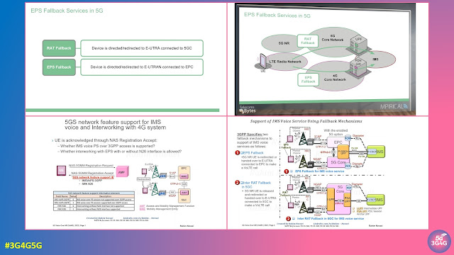
Ralf Kreher explained EPS Fallback mechanism in his post earlier, which is still quite popular. This post contains couple of videos that also explain this procedure. 

The first is a very short and simple tutorial from Mpirical, embedded below:

The second is a slightly technical presentation explaining how 5G system can redirect the 5G VoNR capable device to the 4G system to continue for IMS based VoLTE voice call.

Related Posts:

Tuesday, October 11, 2022

The Role of Connectivity and Devices in Healthcare


Over the last few months I have discussed the role of 5G in different industries as part of various projects. Some of these discussions are part of my blog posts while others aren’t.

5G is often promoted as a panacea for all industries including healthcare. This presentation and video looks not only at 5G but other connectivity options that can be used to provide solutions for healthcare. In addition, this presentation looks at different components of the mobile network and explore the role of devices in healthcare.

Presentation and video below

You can download the slides here.

Related Posts

Saturday, September 10, 2022

CUPS for Flexible U-Plane Processing Based on Traffic Characteristics

I looked at Control and User Plane Separation (CUPS) in a tutorial, nearly five years back here. Since then most focus has been on 5G, not just on my blogs but also from the industry. 

Earlier this year, NTT Docomo's Technical Journal looked at CUPS for Flexible U-Plane Processing Based on Traffic Characteristics. The following is an extract from the article:

At the initial deployment phase of 5th Generation mobile communication systems (5G), the 5G Non-Stand-Alone (NSA) architecture was widely adopted to realize 5G services by connecting 5G base stations to the existing Evolved Packet Core (EPC). As applications based on 5G become more widespread, the need for EPC to achieve higher speed and capacity communications, lower latency communications and simultaneous connection of many terminals than ever has become urgent. Specifically, it is necessary to increase the number of high-capacity gateway devices capable of processing hundreds of Gbps to several Tbps to achieve high-speed, high-capacity communications, to distribute gateway devices near base station facilities to achieve even lower latency communications, and to improve session processing performance for connecting massive numbers of terminals simultaneously.

Conventional single gateway devices have both Control Plane (C-Plane) functions to manage communication sessions and control communications, and User Plane (U-Plane) functions to handle communications traffic. Therefore, if the previously assumed balance between the number of sessions and communications capacity is disrupted, either the C-Plane or the U-Plane will have excess processing capacity. In high-speed, high-capacity communications, the C-Plane has excess processing power, and in multiple terminal simultaneous connections, the U-Plane has excess processing power because the volume of communications is small compared to the number of sessions. If the C-Plane and U-Plane can be scaled independently, these issues can be resolved, and efficient facility design can be expected. In addition, low-latency communications require distributed deployment of the U-Plane function near the base station facilities to reduce propagation delay. However, in the distributed deployment of conventional devices with integrated C-Plane and U-Plane functions, the number of sessions and communication volume are unevenly distributed among the gateway devices, resulting in a decrease in the efficiency of facility utilization. Since there is no need for distributed deployment of C-Plane functions, if the C-Plane and U-Plane functions can be separated and the way they are deployed changed according to their characteristics, the loss of facility utilization efficiency related to C-Plane processing capacity could be greatly reduced.

CUPS is an architecture defined in 3GPP TS 23.214 that separates the Serving GateWay (SGW)/Packet data network GateWay (PGW) configuration of the EPC into the C-Plane and U-Plane. The CUPS architecture is designed so that there is no difference in the interface between the existing architecture and the CUPS architecture - even with CUPS architecture deployed in SGW/PGW, opposing devices such as a Mobility Management Entity (MME), Policy and Charging Rules Function (PCRF), evolved NodeB (eNB)/ next generation NodeB (gNB), and SGWs/PGWs of other networks such as Mobile Virtual Network Operator (MVNO) and roaming are not affected. For C-Plane, SGW Control plane function (SGW-C)/PGW Control plane function (PGW-C), and for U-Plane, SGW User plane function (SGW- U)/PGW User plane function (PGW-U) are equipped with call processing functions. By introducing CUPS, C-Plane/U-Plane capacities can be expanded individually as needed. Combined SGW-C/PGW-C and Combined SGW-U/PGW-U can handle the functions of SGW and PGW in common devices. In the standard specification, in addition to SGW/PGW, the Traffic Detection Function (TDF) can also be separated into TDF-C and TDF-U, but the details are omitted in this article.

From above background, NTT DOCOMO has been planning to deploy Control and User Plane Separation (CUPS) architecture to realize the separation of C-Plane and U-Plane functions as specified in 3rd Generation Partnership Project Technical Specification (3GPP TS) 23.214. Separating the C-Plane and U-Plane functions of gateway devices with CUPS architecture makes it possible to scale the C-Plane and U-Plane independently and balance the centralized deployment of C-Plane functions with the distributed deployment of U- Plane functions, thereby enabling the deployment and development of a flexible and efficient core network. In addition to solving the aforementioned issues, CUPS will also enable independent equipment upgrades for C-Plane and U-Plane functions, and the adoption of U-Plane devices specialized for specific traffic characteristics.

In the user perspective, the introduction of CUPS can be expected to dramatically improve the user experience through the operation of facilities specializing in various requirements, and enable further increases in facilities and lower charges to pursue user benefits by improving the efficiency of core network facilities.

Regarding the CUPS architecture, a source of value for both operators and users, this article includes an overview of the architecture, additional control protocols, U-Plane control schemes based on traffic characteristics, and future developments toward a 5G Stand-Alone (5G SA) architecture.

The article is available here.

Related Posts

Thursday, June 16, 2022

What is a Multi-Band Cell?

Multi-band cells became very popular in modern RAN environment and beside many benefits they also come with some challenges for performance measurement and radio network optimization.

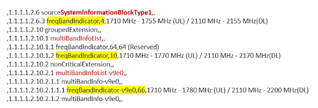
A multi-band cell consists of a default band that shall be used by UEs for initial cell selection and a set of additional frequency band carriers that typically become involved as soon as a dedicated radio bearer (DRB) for payload transmission is established in the radio connection.

The exact configuration of a multi-band cell including all available frequency bands is broadcasted in SIB 1 as shown in the example below.

Different from legacy RAN deployments where – to take the example of a LTE cell – a pair of PCI/eARFCN (Physical Cell Identity/eUTRAN Absolute Radio Frequency Number) always matches a particular ECGI (eUTRAN Cell Global Identity) the multi-band cell has many different PCI/eARFCN combinations belonging to a single ECGI as you can see in the next figure.

Now performance measurement (PM) counters for e.g. call drops are typically counted on the cell ID (ECGI) and thus, in case of mulit-band cells do not reveal on which frequency a radio link failure occurred.

However, knowing the frequency is essential to optimize the radio network and minimize connectivity problems. More detailed information must be collected to find out which of the different frequency bands performs well and which need improvement.

This becomes even more interesting if multi-band cells are used in MORAN RAN sharing scenarios.

In my next blog post I will have a closer look at this special deployment.

Related Posts:

Monday, June 13, 2022

Tutorial on 4G/5G Mobile Network Uplink Working and Challenges

People involved with mobile technology know the challenges with uplink for any generation of mobile network. With increasing data rates in 4G and 5G, the issue has become important as most of the speeds are focused on download but upload speeds are quite poor.

People who follow us across our channels know of many of the presentations we share across them from various sources, not just ours. One such presentation by Peter Schmidt looked at the uplink in details. In fact we recommend following him on Twitter if you are interested in technical details and infrastructure.

The details of his talk as follows:

The lecture highlights the influences on the mysterious part of mobile communications - sources of interference in the uplink and their impact on mobile communication as well as practices for detecting sources of RF interference.

The field strength bar graph of a smartphone (the downlink reception field strength) is only half of the truth when assessing a mobile network coverage. The other half is the uplink, which is largely invisible but highly sensitive to interference, the direction from the end device to the base stations. In this lecture, sources of uplink interference, their effects and measurement and analysis options will be explained.

Cellular network uplink is essential for mobile communication, but nobody can really see it. The uplink can be disrupted by jammers, repeaters, and many other RF sources. When it is jammed, mobile communication is limited. I will show what types of interference sources can disrupt the uplink and what impact this has on cellular usage and how interference hunting can be done.

First I explain the necessary level symmetry of the downlink (from the mobile radio base station - eNodeB to the end device) and the uplink (from the end device back to the eNodeB). Since the transmission power of the end device and eNodeB are very different, I explain the technical background to achieving symmetry. In the following I will explain the problems and possibilities when measuring uplink signals on the eNodeB, it is difficult to look inside the receiver. In comparison, the downlink is very easy to measure, you can see the bars on your smartphone or you can use apps that provide detailed field strength information etc. However, the uplink remains largely invisible. However, if this is disturbed on the eNodeB, the field strength bars on the end device say nothing. I will present a way of observing which some end devices bring on board or can be read out of the chipset with APPs. The form in which the uplink can be disrupted, the effects on communication and the search for uplink sources of disruption will complete the presentation. I will also address the problem of 'passive intermodulation' (PIM), a (not) new source of interference in base station antenna systems, its assessment, measurement and avoidance.

The slides are available here. The original lecture was in German, a dubbed video is embedded below:

If you know of some other fantastic resources that we can share with our audience, please feel free to add them in the comments.

Related Posts

Monday, June 6, 2022

2G/3G Shutdown may Cost Lives as 4G/5G Voice Roaming is a Mess

You have probably heard me a complaining about the pace of VoLTE rollout, 2G/3G shutdowns, 4G Voice roaming, etc. This post highlights all these issues coming together in a dangerous way. People often ask me why is it that it's always just me highlighting the issues. The answer is that there are other people but their voice may not reach you. In this post, I am highlighting presentations by Rudolf van der Berg, Project and programme manager at Stratix Consulting.

Let's start with Rudolf's post from LinkedIn:

Stop the shutdown of 2G and 3G networks to save lives. This is the urgent call I make today and I hope you can help me spread it! Please call on people you know in politics, regulators and emergency services to demand a stop! Call on anyone you know in the GSMA, 3GPP, handset makers (Apple, Samsung, Qualcomm, MediaTek), network builders (Ericsson, Nokia, Huawei) to re-engineer VoLTE to an interoperable standard.

Emergency calls (112, 911) should work anywhere in the world on any phone. For GSM and 3G voice calling it did. You could fly anywhere and call emergency services and in the EU we have the roaming regulation that demands calling like at home. Voice over 4G and 5G hasn't been properly standardized and isn't interoperable between networks, devices, chipsets and firmware. People need to be able to make and receive telephone calls around the world, to each other and to emergency services. Unfortunately even according to sector itself emergency services are at risk from VoLTE. A consumer today can't know whether a phone they bought will make VoLTE calls at home or abroad, nor whether it can reach emergency services. That can't be right!

So please help EENA 112 and me share this message! Thank you #eena2022 (Slide 4 contains a mistake, T-Mo USA hasn't decided on 2G shutdown yet. that is good for availability of 911, though fundamental point remains. Apologies.)

The video and slides are embedded below:

The slides contain many useful references and links, you can download directly from here.

Back in April, iBASIS hosted a VoLTE and 5G Roaming Roundtable. You can watch the video here and download the presentation and whitepaper as well. It contains talks from Kaleido Intelligence, iBASIS, KPN, Bouygues Telecom and Telus. 

The slide from Dutch MNO KPN above highlights the VoLTE Roaming issues they are observing. Other operators will face this issue sooner or later as well. 

The Regulators, GSMA and 3GPP have to come together to fix this important issue for once and all so no lives are lost because of this. Hopefully someone is listening!

Related Posts