Showing posts with label RAN Sharing. Show all posts

Friday 26 August 2022

How Multiband-Cells are used for MORAN RAN Sharing

In the previous blog post I have explained the concept of multi-band cells in LTE networks and promised to explain a bit deeper how such cells can be used in Multi-Operator RAN (MORAN) scenarios. 

MORAN is characterized by the fact that all network resources except the radio carriers and the Home Subscriber Server (HSS) are shared between two or more operators. 

What this means in detail can be see in Step 1 of the figure below. 

The yellow Band #1 spectrum of the multi-band cell is owned by Network Operator 1 while the blue spectrum of Band #2 and Band #3 belongs to Network Operator 2.

Band #1 is the default band. This means if a UE enters the cell is always has to establish the initial RRC signaling connection on Band #1 as shown in step 1.

The spectrum owned by Network Operator 2 comes into the game as soon as a dedicated radio bearer (DRB), in the core network known as E-RAB, is established in this RRC connection. 

Then we see intra-frequency (intra-cell) handover to Band #2 where the RRC signaling connection is continued. Band #3 is added for user plane transport as a secondary "cell" (the term refers to the 3GPP 36.331 RRC specification). 

The reason for this behavior can be explained when looking a frequency bandwidths. 

The default Band #1 is a low frequency band with a quite small bandwidth, e.g. 5 MHz. as it is typically used for providing good coverage in rural areas. Band #2 is also a lower frequency band, but Band #3 is a high frequency band with maximum bandwidth of 20 MHz. So Band #3 brings the highest capacity for user plane transport and that is the reason for the handover to the spectrum owned by Network Operator 2 and the carrier aggregation used on these frequency bands. 

However, due to the higher frequency the footprint of Band #3 is lower compared to the other two frequency bands. 

For UEs at the cell edge (or located in buildings while being served from the outdoor cell) this leads quite often to situations where the radio coverage of Band #3 becomes insufficient. In such cases the UE typically sends a RRC measurement event A2 (means: "The RSRP of the cell is below a certain threshold."). 

If such A2 event is received by the eNB it stops the carrier aggregation transport and releases the Band #3 resources so that all user plane transport continues to run on the limited Band #2 resources as shown in step 3.

And now in the particular eNB I observed a nice algorithm starts that could be seen as a kind of zero-touch network operation although it does not need big data nor artificial intelligence. 

10 seconds after the secondary frequency resources of Band #3 have been deleted they are added again to the connection, but if the UE is still at the same location the next A2 will be reported soon and carrier aggregation will be stopped again for 10 seconds and then the next cycle starts.

This automation loop is carried out endlessly until the UE changes its location or the RRC connection is terminated. 

Related Posts:

Thursday 16 June 2022

What is a Multi-Band Cell?

Multi-band cells became very popular in modern RAN environment and beside many benefits they also come with some challenges for performance measurement and radio network optimization.

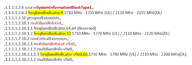
A multi-band cell consists of a default band that shall be used by UEs for initial cell selection and a set of additional frequency band carriers that typically become involved as soon as a dedicated radio bearer (DRB) for payload transmission is established in the radio connection.

The exact configuration of a multi-band cell including all available frequency bands is broadcasted in SIB 1 as shown in the example below.

Different from legacy RAN deployments where – to take the example of a LTE cell – a pair of PCI/eARFCN (Physical Cell Identity/eUTRAN Absolute Radio Frequency Number) always matches a particular ECGI (eUTRAN Cell Global Identity) the multi-band cell has many different PCI/eARFCN combinations belonging to a single ECGI as you can see in the next figure.

Now performance measurement (PM) counters for e.g. call drops are typically counted on the cell ID (ECGI) and thus, in case of mulit-band cells do not reveal on which frequency a radio link failure occurred.

However, knowing the frequency is essential to optimize the radio network and minimize connectivity problems. More detailed information must be collected to find out which of the different frequency bands performs well and which need improvement.

This becomes even more interesting if multi-band cells are used in MORAN RAN sharing scenarios.

In my next blog post I will have a closer look at this special deployment.

Related Posts:

Monday 26 October 2020

Understanding the TCO of a Mobile Network

TCO or 'Total Cost of Ownership' is an important topic for the mobile networks. The service providers use it to ascertain how much the network will cost and based on that they decide what they should charge and how much money could make. 

In this basic tutorial, we looks at the basic costs in the mobile network, eventually looking at the CapEx and OpEx of RAN and look at how some operators try to reduce the these costs. Slides and video embedded below.

Would love to hear your thoughts and anecdotes.

Related Posts:

Tuesday 21 January 2020

How MOCN RAN-Sharing Works

Shared RAN deployment scenarios are an excellent opportunity for mobile network operators to lower their investments on both, network hardware and operational costs by sharing resources.

The MORAN approach where each operator continues to have its dedicated spectrum (= radio network cells) is easy to understand.

However, the Multi-Operator Core Network (MOCN) is a bit more complex, especially if one of the involved operators asks for service assurance KPIs that apply to its - and only its - subscribers. In this case it is a prerequisite to find out which "call" belongs to which core network operator to enable further KPI correlation and aggregation.

The figure below illustrates how this works:

(click on picture for larger version)

In the System Information Block (SIB) 1 of the cell a list of PLMN-IDs is broadcasted followed by a single Tracking Area Code (which can be combined each of the PLMN-IDs to get multiple TAIs) and a single Cell Identity.

Encoding is specified in 3GPP 36.331 (RRC) as follows:

SystemInformationBlockType1 ::=     SEQUENCE {
    cellAccessRelatedInfo              SEQUENCE {
       plmn-IdentityList                 PLMN-IdentityList,
       trackingAreaCode                  TrackingAreaCode,
       cellIdentity                      CellIdentity,

The spec further defines that the ECGI is the CellIdentiy combined with the first (!!!) PLMN-ID from the PLMN-ID List:

CellGlobalIdEUTRA field descriptions
cellIdentity
Identity of the cell within the context of the PLMN.
plmn-Identity
Identifies the PLMN of the cell as given by the first PLMN entry in the plmn-IdentityList in SystemInformationBlockType1.

So there is one and only 1 ECGI per radio cell in the network, but multiple PLMN-IDs and hence, multiple TAI, one fore each core network operator, are broadcasted.

During RRC establishement a particular UE signals on behalf on the selected PLMN-ID information element in the RRC Connection Setup Complete message to which core network operator shall be used.

This information is "translated" by the eNB into ECGI and TAI with different PLMN-IDs. While the ECGI displays the PLMN-ID of the operator that owns the RAN equipment the TAI shows the selected PLMN-ID of the UE's core network operator. 

Related Posts: