Showing posts with label Signalling. Show all posts

Wednesday 24 January 2024

UE Assistance Information in LTE and 5G

I have been asked about the UE Assistance Information (UAI) RRC message a few times before. Generally I have always pointed people back to the LTE/5G specifications but here is a concise video that the telecoms technology training company Mpirical have shared recently:

If you want to dig further into details then please see the RRC specifications: 36.331 for LTE and 38.331 for 5G. 

Over the years I have added quite a few short tutorials from Mpirical on this blog, do check them out below.

Related Posts

Wednesday 12 July 2023

Small Data Transmission (SDT) in LTE and 5G NR

One of the features that was introduced part of 5G NR 3GPP Release 17 is known as Small Data Transmission (SDT). When small amount of data, in case of an IoT device, needs to be sent, there is no need to establish data radio bearers. The information can be sent as part of signalling message. A similar approach is available in case of 4G LTE. 

Quoting from Ofinno whitepaper 'Small Data Transmission: PHY/MAC', 

The SDT in the 3GPP simply refers to data transmission in an inactive state. Specifically, the SDT is a transmission for a short data burst in a connectionless state where a device does not need to establish and teardown connections when small amounts of data need to be sent.

In the 3GPP standards, the inactive state had not supported data transmission until Release 15. The 3GPP standards basically allowed the data transmission when ciphering and integrity protection are achieved during the connection establishment procedure. Therefore, the data transmission can occur after the successful completion of the establishment procedure between the device and network.

The problem arises as a device stays in the connected state for a short period of time and subsequently releases the connection once the small size data is sent. Generally, the device needs to perform multiple transmissions and receptions of control signals to initiate and maintain the connection with a network. As a payload size of the data is relatively smaller compared with the amounts of the control signals, making a connection for the small data transmission becomes more of a concern for both the network and the device due to the control signaling overhead.

The 3GPP has developed the SDT procedure to enable data transmission in the inactive state over the existing LTE and NR standards. The device initiates the SDT procedure by transmitting an RRC request message (e.g., SDT request message) and data in parallel instead of transmitting the data after the RRC request message processed by a network. Additional transmission and/or reception are optional. The device performs this SDT procedure without transition to the connected state (i.e., without making a connection to the network).

The SDT enables for the network to accept data transmission without signaling intensive bearer establishment and authentication procedure required for the RRC connection establishment or resume procedure. For example, in the SDT procedure, the device needs only one immediate transmission of a transport block (TB) that contains data and RRC request message. Furthermore, the device does not need to perform procedures (e.g., radio link monitoring) defined in the connected state since the RRC state is kept as the inactive state. This results in improving the battery life of the device by avoiding control signaling unnecessary for transmission of small size data.

The principle of the SDT is very simple. The network configures radio resources beforehand for the data transmission in the inactive state. For example, if the conditions to use the configured radio resources satisfy, the device transmits data and the RRC request message together via the configured radio resources. In the 3GPP standards, there are two types of the SDT depending on the ways to configure the radio resources: (1) SDT using a random access (RA) and (2) SDT using preconfigured radio resources. 

Figure 2 (top) illustrates different types of the SDT referred in 3GPP LTE and NR standards. The SDT using the random access in LTE and NR standards is referred to as an EDT (early data transmission) and RA-SDT (Random Access based SDT), respectively. For both the EDT and the RA-SDT, the device performs data transmission using shared radio resources of the random access procedure. Thus, the contention with other devices can occur over the access to the shared radio resources. The shared radio resources for the SDT are broadcast by system information and are configured as isolated from the one for a nonSDT RA procedure, i.e., the legacy RA procedure. On the other hands, the CG-SDT uses the preconfigured radio resources dedicated to the device. The SDT using the preconfigured radio resource is referred to as transmission via PUR (Preconfigured Uplink Resource) in the LTE standards. The NR standards refers the SDT using the preconfigured radio resource as CG-SDT (Configured Grant based SDT). The network configures the configuration parameters of the preconfigured radio resources when transiting the device in the connected state to the inactive state. For example, an RRC release message transmitted from the network for a connection release contains the configuration parameters of PUR or CG-SDT. No contention is expected for the SDT using the preconfigured radio resource since the configuration parameters are dedicated to the device. 

You can continue reading the details in whitepaper here. Ofinno has another whitepaper on this topic, 'Small Data Transmission (SDT): Protocol Aspects' here.

3GPP also recently published an article on this topic here. Quoting from the article:

With SDT it is possible for the device to send small amounts of data while remaining in the inactive state. Note that this idea resembles the early GSM systems where SMS messages where sent via the control signalling; that is, transferring small amounts of data while the mobile did not have a (voice) connection.

SDT is a procedure which allows data and/or signalling transmission while the device remains in inactive state without transitioning to connected state. SDT is enabled on a radio bearer basis and is initiated by the UE only if less than a configured amount of UL data awaits transmission across all radio bearers for which SDT is enabled. Otherwise the normal data transmission scheme is used.

With SDT the data is transmitted quickly on the allocated resource. The IoT device initiates the SDT procedure by transmitting an RRC request message and payload data in parallel, instead of the usual procedure where the data is transmitted after the RRC request message is processed by a network.

It is not only the speed and the reduced size of the transmitted data which make SDT such a suitable process for IoT devices. Since the device stays in the inactive state, it does not have to perform many tasks associated with the active state. This further improves the battery life of the IoT device. Additional transmission and/or reception are optional.

There are two ways of performing SDT:

  1. via random access (RA-SDT)
  2. via preconfigured radio resources (CG-SDT)

Random Access SDT

With RA-SDT, the IoT device does not have a dedicated radio resource, and it is possible that the random access message clashes with similar RA-SDT random access messages from other IoT devices. The device gets to know the radio resources for the RA procedure from system information messages, in a similar way to non RA-SDT devices. However, the RA radio resources for SDT and non SDT devices are kept separate; that is, these device types do not interfere with each other in random access

The RA-SDT procedure can be a two-step or a four-step random access procedure. In two-step procedure the payload data is already sent with the initial random access message, whereas in four-step procedure the device first performs contention resolution with the random access request - random access response message pair, and then sends the UL payload with RRC Resume Request. The procedure may continue with further uplink and downlink small data transmissions, and then it is terminated with an RRC Release from the network.

Below are the signalling diagrams for both two-step and four-step RA-SDT procedures. Note that in both cases the UE stays in the RRC inactive state during the whole process.

Configured Grant SDT

For CG-SDT, the radio resources are allocated periodically based on the estimation of the UE’s traffic requirements. This uplink scheduling method is called Configured Grant (CG). With CG-SDT there will be no message clashes with other IoT devices since the radio resources are dedicated for each device. The resource allocation is signalled to the IoT device by the network when the device leaves the connected state.

If the amount of data in the UE's tx buffer is larger than a defined limit, then the data transmission is done using the normal non-SDT procedure.

For SDT process, the device selects the CG-SDT as the SDT type if the resources for the CG-SDT are configured on the selected uplink carrier. If the resources for the CG-SDT are unavailable or invalid, the RA-SDT or the non-SDT RA procedure will be chosen if those are configured. If no SDT type configuration is available then a normal non-SDT data transmission is performed.

With IoT devices proliferating, it makes sense to optimise data transfer and anything else that will reduce the power consumption and let the battery in the devices last for much longer.

Related Posts

Wednesday 30 November 2022

Disaster Roaming in 3GPP Release-17

One way all operators in a country/region/geographic area differentiate amongst themselves is by the reach of their network. It's not in their interest to allow national roaming. Occasionally a regulator may force them to allow this, especially in rural or remote areas. Another reason why operators may choose to allow roaming is to reduce their network deployment costs. 

In case of disasters or emergencies, if an operator's infrastructure goes down, the subscribers of that network can still access other networks for emergencies but not for normal services. This can cause issues as some people may not be able to communicate with friends/family/work. 

A recent example of this kind of outage was in Japan, when the KDDI network failed. Some 39 million users were affected and many of them couldn't even do emergency calls. If Disaster Roaming was enabled, this kind of situation wouldn't occur.

South Korea already has a proprietary disaster roaming system in operation since 2020, as can be seen in the video above. This automatic disaster roaming is only available for 4G and 5G.

In 3GPP Release-17, Disaster Roaming has been specified for LTE and 5G NR. In case of LTE, the information is sent in SIB Type 30 while in 5G it is in SIB Type 15.

3GPP TS 23.501 section 5.40 provides summary of all the other information needed for disaster roaming. Quoting from that:

Subject to operator policy and national/regional regulations, 5GS provides Disaster Roaming service (e.g. voice call and data service) for the UEs from PLMN(s) with Disaster Condition. The UE shall attempt Disaster Roaming only if:

  • there is no available PLMN which is allowable (see TS 23.122 [17]);
  • the UE is not in RM-REGISTERED and CM-CONNECTED state over non-3GPP access connected to 5GCN;
  • the UE cannot get service over non-3GPP access through ePDG;
  • the UE supports Disaster Roaming service;
  • the UE has been configured by the HPLMN with an indication of whether Disaster roaming is enabled in the UE set to "disaster roaming is enabled in the UE" as specified in clause 5.40.2; and
  • a PLMN without Disaster Condition is able to accept Disaster Inbound Roamers from the PLMN with Disaster Condition.

In this Release of the specification, the Disaster Condition only applies to NG-RAN nodes, which means the rest of the network functions except one or more NG-RAN nodes of the PLMN with Disaster Condition can be assumed to be operational.

A UE supporting Disaster Roaming is configured with the following information:

  • Optionally, indication of whether disaster roaming is enabled in the UE;
  • Optionally, indication of 'applicability of "lists of PLMN(s) to be used in disaster condition" provided by a VPLMN';
  • Optionally, list of PLMN(s) to be used in Disaster Condition.

The Activation of Disaster Roaming is performed by the HPLMN by setting the indication of whether Disaster roaming is enabled in the UE to "disaster roaming is enabled in the UE" using the UE Parameters Update Procedure as defined in TS 23.502 [3]. The UE shall only perform disaster roaming if the HPLMN has configured the UE with the indication of whether disaster roaming is enabled in the UE and set the indication to "disaster roaming is enabled in the UE". The UE, registered for Disaster Roaming service, shall deregister from the PLMN providing Disaster Roaming service if the received indication of whether disaster roaming is enabled in the UE is set to "disaster roaming is disabled in the UE".

Check the specs out for complete details. 

From my point of view, it makes complete sense to have this enabled for the case when disaster strikes. Earlier this year, local governments in Queensland, Australia were urging the Federal Government to immediately commit to a trial of domestic mobile roaming during emergencies based on the recommendation by the Regional Telecommunications Independent Review Committee. Other countries and regions would be demanding this sooner or later as well. It is in everyone's interest that the operators enable this as soon as possible.

Related Posts:

Saturday 10 September 2022

CUPS for Flexible U-Plane Processing Based on Traffic Characteristics

I looked at Control and User Plane Separation (CUPS) in a tutorial, nearly five years back here. Since then most focus has been on 5G, not just on my blogs but also from the industry. 

Earlier this year, NTT Docomo's Technical Journal looked at CUPS for Flexible U-Plane Processing Based on Traffic Characteristics. The following is an extract from the article:

At the initial deployment phase of 5th Generation mobile communication systems (5G), the 5G Non-Stand-Alone (NSA) architecture was widely adopted to realize 5G services by connecting 5G base stations to the existing Evolved Packet Core (EPC). As applications based on 5G become more widespread, the need for EPC to achieve higher speed and capacity communications, lower latency communications and simultaneous connection of many terminals than ever has become urgent. Specifically, it is necessary to increase the number of high-capacity gateway devices capable of processing hundreds of Gbps to several Tbps to achieve high-speed, high-capacity communications, to distribute gateway devices near base station facilities to achieve even lower latency communications, and to improve session processing performance for connecting massive numbers of terminals simultaneously.

Conventional single gateway devices have both Control Plane (C-Plane) functions to manage communication sessions and control communications, and User Plane (U-Plane) functions to handle communications traffic. Therefore, if the previously assumed balance between the number of sessions and communications capacity is disrupted, either the C-Plane or the U-Plane will have excess processing capacity. In high-speed, high-capacity communications, the C-Plane has excess processing power, and in multiple terminal simultaneous connections, the U-Plane has excess processing power because the volume of communications is small compared to the number of sessions. If the C-Plane and U-Plane can be scaled independently, these issues can be resolved, and efficient facility design can be expected. In addition, low-latency communications require distributed deployment of the U-Plane function near the base station facilities to reduce propagation delay. However, in the distributed deployment of conventional devices with integrated C-Plane and U-Plane functions, the number of sessions and communication volume are unevenly distributed among the gateway devices, resulting in a decrease in the efficiency of facility utilization. Since there is no need for distributed deployment of C-Plane functions, if the C-Plane and U-Plane functions can be separated and the way they are deployed changed according to their characteristics, the loss of facility utilization efficiency related to C-Plane processing capacity could be greatly reduced.

CUPS is an architecture defined in 3GPP TS 23.214 that separates the Serving GateWay (SGW)/Packet data network GateWay (PGW) configuration of the EPC into the C-Plane and U-Plane. The CUPS architecture is designed so that there is no difference in the interface between the existing architecture and the CUPS architecture - even with CUPS architecture deployed in SGW/PGW, opposing devices such as a Mobility Management Entity (MME), Policy and Charging Rules Function (PCRF), evolved NodeB (eNB)/ next generation NodeB (gNB), and SGWs/PGWs of other networks such as Mobile Virtual Network Operator (MVNO) and roaming are not affected. For C-Plane, SGW Control plane function (SGW-C)/PGW Control plane function (PGW-C), and for U-Plane, SGW User plane function (SGW- U)/PGW User plane function (PGW-U) are equipped with call processing functions. By introducing CUPS, C-Plane/U-Plane capacities can be expanded individually as needed. Combined SGW-C/PGW-C and Combined SGW-U/PGW-U can handle the functions of SGW and PGW in common devices. In the standard specification, in addition to SGW/PGW, the Traffic Detection Function (TDF) can also be separated into TDF-C and TDF-U, but the details are omitted in this article.

From above background, NTT DOCOMO has been planning to deploy Control and User Plane Separation (CUPS) architecture to realize the separation of C-Plane and U-Plane functions as specified in 3rd Generation Partnership Project Technical Specification (3GPP TS) 23.214. Separating the C-Plane and U-Plane functions of gateway devices with CUPS architecture makes it possible to scale the C-Plane and U-Plane independently and balance the centralized deployment of C-Plane functions with the distributed deployment of U- Plane functions, thereby enabling the deployment and development of a flexible and efficient core network. In addition to solving the aforementioned issues, CUPS will also enable independent equipment upgrades for C-Plane and U-Plane functions, and the adoption of U-Plane devices specialized for specific traffic characteristics.

In the user perspective, the introduction of CUPS can be expected to dramatically improve the user experience through the operation of facilities specializing in various requirements, and enable further increases in facilities and lower charges to pursue user benefits by improving the efficiency of core network facilities.

Regarding the CUPS architecture, a source of value for both operators and users, this article includes an overview of the architecture, additional control protocols, U-Plane control schemes based on traffic characteristics, and future developments toward a 5G Stand-Alone (5G SA) architecture.

The article is available here.

Related Posts

Friday 26 August 2022

How Multiband-Cells are used for MORAN RAN Sharing

In the previous blog post I have explained the concept of multi-band cells in LTE networks and promised to explain a bit deeper how such cells can be used in Multi-Operator RAN (MORAN) scenarios. 

MORAN is characterized by the fact that all network resources except the radio carriers and the Home Subscriber Server (HSS) are shared between two or more operators. 

What this means in detail can be see in Step 1 of the figure below. 

The yellow Band #1 spectrum of the multi-band cell is owned by Network Operator 1 while the blue spectrum of Band #2 and Band #3 belongs to Network Operator 2.

Band #1 is the default band. This means if a UE enters the cell is always has to establish the initial RRC signaling connection on Band #1 as shown in step 1.

The spectrum owned by Network Operator 2 comes into the game as soon as a dedicated radio bearer (DRB), in the core network known as E-RAB, is established in this RRC connection. 

Then we see intra-frequency (intra-cell) handover to Band #2 where the RRC signaling connection is continued. Band #3 is added for user plane transport as a secondary "cell" (the term refers to the 3GPP 36.331 RRC specification). 

The reason for this behavior can be explained when looking a frequency bandwidths. 

The default Band #1 is a low frequency band with a quite small bandwidth, e.g. 5 MHz. as it is typically used for providing good coverage in rural areas. Band #2 is also a lower frequency band, but Band #3 is a high frequency band with maximum bandwidth of 20 MHz. So Band #3 brings the highest capacity for user plane transport and that is the reason for the handover to the spectrum owned by Network Operator 2 and the carrier aggregation used on these frequency bands. 

However, due to the higher frequency the footprint of Band #3 is lower compared to the other two frequency bands. 

For UEs at the cell edge (or located in buildings while being served from the outdoor cell) this leads quite often to situations where the radio coverage of Band #3 becomes insufficient. In such cases the UE typically sends a RRC measurement event A2 (means: "The RSRP of the cell is below a certain threshold."). 

If such A2 event is received by the eNB it stops the carrier aggregation transport and releases the Band #3 resources so that all user plane transport continues to run on the limited Band #2 resources as shown in step 3.

And now in the particular eNB I observed a nice algorithm starts that could be seen as a kind of zero-touch network operation although it does not need big data nor artificial intelligence. 

10 seconds after the secondary frequency resources of Band #3 have been deleted they are added again to the connection, but if the UE is still at the same location the next A2 will be reported soon and carrier aggregation will be stopped again for 10 seconds and then the next cycle starts.

This automation loop is carried out endlessly until the UE changes its location or the RRC connection is terminated. 

Related Posts:

Tuesday 16 August 2022

Managing 5G Signalling Storms with Service Communication Proxy (SCP)

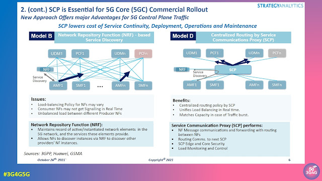
When we made our 5G Service Based Architecture (SBA) tutorial some four years back, it was based on Release-15 of the 3GPP standards. All Network Functions (NFs) simply sent discovery requests to the Network Repository Function (NRF). While this works great for trials and small scale deployments it can also lead to issues as can be seen in the slide above.

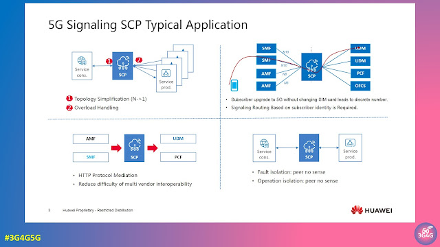
In 3GPP Release-16 the Service Communication Proxy (SCP) has now been introduced to allow the Control Plane network to handle and prioritize massive numbers of requests in real time. The SCP becomes the control point that mediates all Signalling and Control Plane messages in the network core.

SCP routing directs the flow of millions of simultaneous 5G function requests and responses for network slicing, microservice instantiation or edge compute access. It also plays a critical role in optimizing floods of discovery requests to the NRF and in overall Control Plane load balancing, traffic prioritization and message management.

A detailed whitepaper on '5G Signaling and Control Plane Traffic Depends on Service Communications Proxy (SCP)' by Strategy Analytics is available on Huawei's website here. This report was a follow on from the 'Signaling — The Critical Nerve Center of 5G Networks' webinar here.

Related Posts:

Thursday 16 June 2022

What is a Multi-Band Cell?

Multi-band cells became very popular in modern RAN environment and beside many benefits they also come with some challenges for performance measurement and radio network optimization.

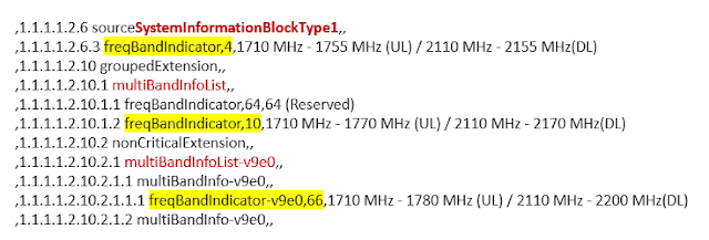
A multi-band cell consists of a default band that shall be used by UEs for initial cell selection and a set of additional frequency band carriers that typically become involved as soon as a dedicated radio bearer (DRB) for payload transmission is established in the radio connection.

The exact configuration of a multi-band cell including all available frequency bands is broadcasted in SIB 1 as shown in the example below.

Different from legacy RAN deployments where – to take the example of a LTE cell – a pair of PCI/eARFCN (Physical Cell Identity/eUTRAN Absolute Radio Frequency Number) always matches a particular ECGI (eUTRAN Cell Global Identity) the multi-band cell has many different PCI/eARFCN combinations belonging to a single ECGI as you can see in the next figure.

Now performance measurement (PM) counters for e.g. call drops are typically counted on the cell ID (ECGI) and thus, in case of mulit-band cells do not reveal on which frequency a radio link failure occurred.

However, knowing the frequency is essential to optimize the radio network and minimize connectivity problems. More detailed information must be collected to find out which of the different frequency bands performs well and which need improvement.

This becomes even more interesting if multi-band cells are used in MORAN RAN sharing scenarios.

In my next blog post I will have a closer look at this special deployment.

Related Posts:

Thursday 4 November 2021

Voice over New Radio (VoNR) Establishment and Release between NG RAN and 5G Core

In this video I explain how QoS Flows for VoNR are established and released especially on N2 reference point between 5G Core and NG RAN.

The pervious video about generic aspects of "QoS Flow Establishments in 5G Standalone RAN and Core" you will find in the first link of the Related Posts listed below:

Tuesday 12 October 2021

Friday 5 March 2021

How to Identify Network Slices in NG RAN

In my last post I described how NG RAN resources can be divided into network slices. 

Now I would like to show how these network slices and the traffic they carry can be identified. 

The key to this is a parameter from the NG Application Protocol (NGAP) called the Single Network Slice Selection Assistance Information (S-NSSAI). When configuring virtual network functions in NG RAN there are lists of S-NSSAI exchanged, e.g. between gNB-CU CP and AMF during NGAP Setup procedure, to negotiate which network slices have to be supported in general. 

When it comes to connection establishment starting with NGAP Initial Context Setup for each PDU session that is established its individual S-NSSAI is signaled. 

The S-NSSAI - as show in the figure below - consists of two parameters, the Slice/Service Type (SST - 8 bit) and the optional Slice Differentiator (SD - 24 bit). The exact format and numbering ranges are defined in 3GPP 23.003.

3GPP 23.501 defines a set of default values for SST as listed in the following table:

Slice/Service type

SST value

Characteristics

eMBB


1

Slice suitable for the handling of 5G enhanced Mobile Broadband.

URLLC

2

Slice suitable for the handling of ultra- reliable low latency communications.

MIoT

3

Slice suitable for the handling of massive IoT.

V2X

4

Slice suitable for the handling of V2X services.

So when looking back at the figure it emerges that for each subscriber represented by an IMSI the SST allows to identify which services are running. 

On the other hand allows to see if in which virtual network the subscriber is active. In my example I have defined that the resources are shared among a Public MNO that I consider the owner of the network hardware and two different private (campus) networks. While IMSI 1 and IMSI 2 are not allowed to use any other network slice the IMSI 3 is allowed to "roam" betweent the public slice and the two private network slices. This explains why a slice-specific authentication functionality as defined in Rel. 16 is necessary. 

Related Posts:

Friday 15 January 2021

UE Radio Capability Signaling Optimization (RACS) in Rel. 16

The data volume of UE Radio Capability Information defined in 3GPP 38.306 is already high and will further increase starting with Rel. 16 due to additional supported bands and other features.

Due to this 3GPP has standardized in Release 16 what is called UE Radio Capability Signaling Optimization (RACS) for both, E-UTRAN/EPS and NG RAN/NGC networks. 

Release 16 RACS does not apply to NB-IoT.

The first key element of this feature set is the introduction of a new UE Radio Capability ID that is structured as defined in 3GPP 23.003 and shown in figure 1 below:

UE Radio Capability ID
Figure 1: UE Radio Capability ID according to 3GPP 23.003

The components of this new ID are:

  •    TF - Type Field (TF): identifies the type of UE radio capability ID.
            Type = 0 -> manufacturer-assigned UE radio capability ID
            Type = 1 -> network-assigned UE radio capability ID

  •  The Version ID configured by the UE Capability Management Function (UCMF) that is part of the EPS/5GC. The Version ID value makes it possible to detect whether a UE Radio Capability ID is current or outdated.

·      The Radio Configuration Identifier (RCI) identifies the UE radio configuration.

The PLMN-assigned UE Radio Capability ID is assigned to the UE using the Non-Access Stratum UE Configuration Update Command or Registration Accept message (figure 2).

Figure 2: PLMN-assigned UE Radio Capability Update according to 3GPP 23.743

The new UCMF (UE radio Capability Management Function) stores All UE Radio Capability ID mappings in a PLMN and is responsible for assigning every PLMN-assigned UE Radio Capability ID.

Due to introduction of the UMCM in the core networks the new Nucmf service-based interface is defined for the 5GC and new S17 reference point is defined for the EPS as shown in figure 3.

Figure 3: Network Architecture with UCMF according to 3GPP 21.916

Each UE Radio Capability ID stored in the UCMF can be associated to one or both UE radio capabilities formats specified in 3GPP TS 36.331 [LTE RRC] and 3GPP TS 38.331 [NR RRC]. The AMF must only be able ot handle the NR RRC format while the MME uses the LTE RRC format. Which format is required by the UCMF is configurable.

If at any time the AMF/MME has neither a valid UE Radio Capability ID nor any stored UE radio capabilities for the UE, the AMF/MME may trigger the RAN to provide the UE Radio Capability information and subsequently request the UCMF to allocate a UE Radio Capability ID.

In NG RAN the UE Capability Request can be requested by the AMF as a flag in any NGAP Downlink NAS Transport message or by sending a NGAP UE Radio Capability Check Request (for checking compatibility of IMS voice capabilities). This triggers a NR RRC UE Capability Transfer procedure and subsequently NGAP UE Radio Capability Info Indication or NGAP UE Radio Capability Check Response (for IMS voice support parameters).

Using the NGAP UE Capability ID Mapping procedure the NG RAN node is able to request the most recent UE Capability ID mapping information from the core network functions AMF/UCMF. The same functionality is implemented in S1AP for signaling between eNB and MME/UCMF.

If the volume of the LTE/NR RRC UE Capability to be sent by the UE is larger than the maximum supported size of a PDCP SDU (specified in 3GPP 38.323) then the UE Capability Info can be transported in LTE/NR RRC using a chain of UL Dedicated Message Segment messages.

Figure 4: RRC UL Dedicated Segment Message transporting UE Radio Capability Information according to 3GPP 36.331 and 38.331

Each of these message will have a dedicated segment number and the last one has the rrc-MessageSegmentType =  “lastSegment”, which triggers reassembly of the orignal UE Capabability information in the receiving entity.

Thursday 17 December 2020

Conditional Handover (Rel. 16) Explained

Although a couple of SON mobility robustness features have been introduced in LTE radio networks it is still a common problem in some network areas that a high number of handover failures leads to higher drop rates and large numbers of RRC Re-Establishments.

Often these problems occur due to quickly changing radio conditions in the handover preparation phase or after handover execution attempt. 

SON algorithms cannot cope with these dynamic changes of the environment, but improvement is possible if the UE itself is enabled to constantly monitor the radio quality during the handover procedure and finally select the best possible target cell from a list of candidate neighbors. This new feature defined in 3GPP Release 16 for both, NG RAN (5G SA NR) as well as E-UTRAN (LTE), is called "Conditional Handover". The figure below illustrates how it works.

(click on the picture to enlarge)

Step 1 is the RRC Measurement Report indicating that handover to a neighbor cell is required. However, this message contains a list of candidate neighbor cells.

In the figure it is assumed that each of these candidate cells is controlled by a different gNB. Hence, 3 XnAP Handover Preparation procedures are performed and each potential target gNB allocates radio resources for the UE and provides a handover command (NR RRC Reconfiguration message) that is sent back to the source gNB (step 2).

In step 3 the source gNB builds the conditional handover command, which is a NR RRC Reconfiguration message that contains a list of conditional reconfiguration options plus additional RRC measurement configurations that enable the UE to find out which of the possible target cells is the best fit. 

In step 4 the UE makes its handover decision and moves to the cell controlled by target gNB 1.

Here it sends in step 5 the NR RRC Reconfiguration Complete message. 

The target gNB 1 detects the handover completion based on the reception of the NR RRC Reconfiguration Complete message, performs NGAP Path Switch procedure (not shown in figure) and triggers the release of the UE context in source gNB on behalf of sending the XnAP UE Context Release message (step 6).

With this information the source gNB also detects the successful handover completion and orders in step 7 the release of the radio resources provided by target gNB 2 and 3 to which it sends the new XnAP Conditional Handover Cancel message.

As mentioned before the conditional handover is also possible for LTE radio connections. In this case X2AP is used instead of XnAP and LTE RRC instead of NR RRC.

The conditional handover can be performed for all kind of intra-eNB/gNB handover and X2/Xn handover. However, S1/N2 (NG-C) conditional handover is not allowed.


Tuesday 17 November 2020

5G Non IP Data Delivery and Lightweight M2M (LwM2M) over NIDD

Earlier this year, MediaTek had announced that its MT2625 NB-IoT chip has been validated for LwM2M over NIDD on SoftBank Corp.’s cellular network across Japan. This achievement marks the first global commercial readiness of LwM2M over NIDD; a secure, ultra-efficient IoT communications technique that is being adopted by operators worldwide. The benefits of LwM2M over NIDD include security improvements, cost-efficient scalability and reduced power consumption.

LwM2M over NIDD is a combination of the communication technology "NIDD (Non-IP Data Delivery)" that does not use an IP address in LTE communication NB-IoT for IoT and the device management protocol "LwM2M (Lightweight M2M)" advocated by the Open Mobile Alliance. It's been a while since I wrote about Open Mobile Alliance on this blog. OMA SpecWorks is the successor brand to the Open Mobile Alliance. You can read all about it here.


OMA SpecWorks’ LightweightM2M is a device management protocol designed for sensor networks and the demands of a machine-to-machine (M2M) environment. With LwM2M, OMA  SpecWorks has responded to demand in the market for a common standard for managing lightweight and low power devices on a variety of networks necessary to realize the potential of IoT. The LwM2M protocol, designed for remote management of M2M devices and related service enablement, features a modern architectural design based on REST, defines an extensible resource and data model and builds on an efficient secure data transfer standard called the Constrained Application Protocol (CoAP). LwM2M has been specified by a group of industry experts at the OMA SpecWorks Device Management Working Group and is based on protocol and security standards from the IETF.

You can get all the LwM2M resources here and the basic specs of 'Lightweight M2M 1.1: Managing Non-IP Devices in Cellular IoT Networks' here.
The 5G Americas whitepaper 'Wireless Technology Evolution Towards 5G: 3GPP Release 13 to Release 15 and Beyond' details how Current Architecture for 3GPP Systems for IOT Service Provision and Connectivity to External Application Servers. It also talks about Rel-13 Cellular IoT EPS Optimizations which provide improved support of small data transfer over control plane and user plane. Control Plane CIoT EPS Optimization transports user data (measurements, ID, status, etc.) via MME by encapsulating user data in NAS PDUs and reduces the total number of control plane messages when handling a short data transaction. Control Plane CIoT EPS optimization, designed for small infrequent data packets, can also be used for larger data bursts depending in UE Radio capability.

User data transported using the Control Plane CIoT EPS Optimization, has special characteristics, as different mobility anchor and termination nodes.

Therefore, the Preferred Network Behavior signaling must include information on:
  • Whether Control Plane CIoT EPS optimization is supported
  • Whether User Plane CIoT EPS optimization is supported
  • Whether Control Plane CIoT EPS optimization is preferred or whether User Plane CIoT EPS optimization is preferred
These optimizations have enabled:
  • Non-IP Data Delivery (NIDD) for both: mobile originated and mobile terminated communications, by using SCEF (Service Capability Exposure Function) or SGi tunneling. However, it has to be taken into account that Non-IP PDUs may be lost and its sequence is not guaranteed
  • For IP data, the UE and MME may perform header compression based on Robust Header Compression (ROHC) framework
  • NB-IoT UE can attach but not activate any PDN connection
  • High latency communication handled by the buffering of downlink data (in the Serving GW or the MME)
  • SMS transfer
  • EPS Attach, TA Update and EPS Detach procedures for NB-IoT only UEs, with SMS service request
  • Procedures for connection suspend and resume are added
  • Support for transfer of user plane data without the need for using the Service Request procedure to establish Access Stratum context in the serving eNodeB and UE
When selecting an MME for a UE that is using the NB-IoT RAT, and/or for a UE that signals support for CIoT EPS Optimizations in RRC signaling, the eNodeB’s MME selection algorithm shall select an MME taking into account its Release 13 NAS signaling protocol.

Mpirical has a nice short video explaining 5G Non IP Data Delivery. It is embedded below.

IoT has not taken off as expected and prophesised for years. While the OMASpecWorks is doing some fantastic work by defining simplified approach for IoT deployment, its current member list doesn't have enough operators to drive the uptake required for its spec adoption. They would argue that it doesn't matter how many members there are as the NIDD approach is completely optional and over-the-top. Let's wait and see how it progresses.

Related Posts:

Wednesday 7 October 2020

Understanding the Dual Active Protocol Stack (DAPS) Handover in 5G


In this video I explain the principles and signaling procedures related to the DAPS handover.

The DAPS handover is a new feature for URLLC services defined by 3GPP in Rel. 16.

Thursday 3 September 2020

Two Types of SMS in 5G


GSMA recently published updated "5G Implementation Guidelines: SA Option 2". It explains the two types of SMS in 5G, the same way there were 2 types of SMS in LTE.

Within 5GC, SMS Function (SMSF) supports SMS over NAS (SMSoNAS) defined in 3GPP TS 23.501. Besides, SMSoIP can also be considered as IMS based SMS solution under 5G network. SMSoIP can be deployed simultaneously with voice service over IMS to provide both voice and short message service. It is recommended to use SMSoNAS solution if voice services over IMS is not supported or for a 5G data card/Machine Type Communications (MTC)/Non-IMS device without voice service. The network architecture of SMSoIP and SMSoNAS is shown in Figure.
Mpirical explains it in the video as embedded below:


You may also find "5G SMS is Very Real and Here to Stay" by William Dudley useful. It covers a lot of technical details and signalling. It's available here.

Related  posts:

Monday 27 July 2020

Key Technology Aspects of 5G Security by Rohde & Schwarz


The 3G4G page contains a lot of useful papers and links to security here but we have also looked at evolution of security from 4G to 5G here. Rohde & Schwarz has a short 8-minute video in which wireless technology manager, Reiner Stuhlfauth, explains the key technology aspects ensuring 5G security. The video is embedded below.


Related Links:

Sunday 19 July 2020

Mobile Initiated Connection Only (MICO) mode in 5G System


Mobile Initiated Connection Only (MICO) mode is designed for IoT devices that send small amounts of data and do not need to be paged. An example of this could be a smart bin that sends a message to the waste collection company saying it is 50% full, etc. This way the bin emptying lorry can plan to empty it in the next collection round. Here there is no reason to page the bin as there is no mobile terminated data that would be required.

MICO mode has to be negotiated between the device and AMF in 5GC. A device in MICO mode cannot be paged as it would not listen to paging to conserve battery power. This extreme power saving mode can ensure that the battery can last for very long time, ideally years thereby making this vision of billions of connected IoT devices a reality.


In an earlier post on RRC Inactive state, we looked at NAS states, along with RRC states. When the UE is in MICO mode, the AMF in 5GC will consider the UE to be unreachable when it is in CM-IDLE state. In addition, a periodic registration timer is also allocated to the MICO mode UEs. The UE has to confirm the MICO mode again during registration update.

The video and presentation are embedded below:


Related Posts:

Friday 17 July 2020

A Look into 5G Virtual/Open RAN - Part 7: Change of gNB-CU-UP without Handover

This will be the last part of my series about Virtual/Open RAN signaling procedures. In this final post (although not the last one on this blog) I would like to present a very unique procedure that emerges from the facts of virtualization and automation of the RAN. And again I would like to present the big picture overview of the scenario that is called "Change of gNB-CU UP" (without handover). The full message flow (ladder diagram) can be found in 3GPP 38.401, chapter 8.9.5.

In the same chapter one can read that the trigger point for starting a change of the gNB-CU UP is quite vague. 3GPP writes: "e.g. a measurement report". However, which particular measurement event should trigger such a procedure? Even when looking into the Rel. 16 versions of 3GPP 38.331 (NR RRC) it becomes evident that all measurement events that are not dealing with NR sidelink or V2X connectivity are triggered by changing reference signal strength or rising interference. 

However, in case of a gNB-CU UP change without handover the UE does not move to a different cell. This makes me think - correct me if I am wrong - the true trigger points for this procedures come form a different entity, e.g. from the AI-driven policies and algorithms of the RAN Intelligence Controller (RIC) that is a fundamental element of the Open RAN architecture.


So what is necessary from a signaling perspective to change the gNB-CU UP during an ongoing connection?

There are new transport network resources aka GTP/IP-Tunnels required to steer the user plane traffic to and through the RAN. A new F1-U tunnel is necessary as well a a new NG-U tunnel, because also the user plane traffic between RAN and the UPF in the 5G core network must be exchange using a new route.

When it is clear which new UP transport tunnels need to be established (and which old ones need to be deleted) it is really simple to understand the overall scenario.

A F1AP UE Context Modification procedure is performed to switch the F1-U tunnel. NGAP Path Switch procedure is performed to switch the NG-U tunnel. And an E1AP Bearer Context Modification procedure is the prerequisite, because it delivers the new UL GTP-TEID for the F1-U tunnel as well as the new DL GTP-TEID for the NG-U tunnel.

Unfortunately the authors of 3GPP 38.401 are not very precise when mentioning protocol procedures defined in other specs. Thus, they speak about "bearer modification" when looking at F1AP and "Path Update" for NGAP.

It is not a big deal, but something you just need to know if you want to analyze real-world message flows of this scenario.

Related Posts: