Showing posts with label EPS. Show all posts

Thursday 20 October 2022

EPS Fallback Mechanism in 5G Standalone Networks

Ralf Kreher explained EPS Fallback mechanism in his post earlier, which is still quite popular. This post contains couple of videos that also explain this procedure. 

The first is a very short and simple tutorial from Mpirical, embedded below:

The second is a slightly technical presentation explaining how 5G system can redirect the 5G VoNR capable device to the 4G system to continue for IMS based VoLTE voice call.

Related Posts:

Saturday 10 September 2022

CUPS for Flexible U-Plane Processing Based on Traffic Characteristics

I looked at Control and User Plane Separation (CUPS) in a tutorial, nearly five years back here. Since then most focus has been on 5G, not just on my blogs but also from the industry. 

Earlier this year, NTT Docomo's Technical Journal looked at CUPS for Flexible U-Plane Processing Based on Traffic Characteristics. The following is an extract from the article:

At the initial deployment phase of 5th Generation mobile communication systems (5G), the 5G Non-Stand-Alone (NSA) architecture was widely adopted to realize 5G services by connecting 5G base stations to the existing Evolved Packet Core (EPC). As applications based on 5G become more widespread, the need for EPC to achieve higher speed and capacity communications, lower latency communications and simultaneous connection of many terminals than ever has become urgent. Specifically, it is necessary to increase the number of high-capacity gateway devices capable of processing hundreds of Gbps to several Tbps to achieve high-speed, high-capacity communications, to distribute gateway devices near base station facilities to achieve even lower latency communications, and to improve session processing performance for connecting massive numbers of terminals simultaneously.

Conventional single gateway devices have both Control Plane (C-Plane) functions to manage communication sessions and control communications, and User Plane (U-Plane) functions to handle communications traffic. Therefore, if the previously assumed balance between the number of sessions and communications capacity is disrupted, either the C-Plane or the U-Plane will have excess processing capacity. In high-speed, high-capacity communications, the C-Plane has excess processing power, and in multiple terminal simultaneous connections, the U-Plane has excess processing power because the volume of communications is small compared to the number of sessions. If the C-Plane and U-Plane can be scaled independently, these issues can be resolved, and efficient facility design can be expected. In addition, low-latency communications require distributed deployment of the U-Plane function near the base station facilities to reduce propagation delay. However, in the distributed deployment of conventional devices with integrated C-Plane and U-Plane functions, the number of sessions and communication volume are unevenly distributed among the gateway devices, resulting in a decrease in the efficiency of facility utilization. Since there is no need for distributed deployment of C-Plane functions, if the C-Plane and U-Plane functions can be separated and the way they are deployed changed according to their characteristics, the loss of facility utilization efficiency related to C-Plane processing capacity could be greatly reduced.

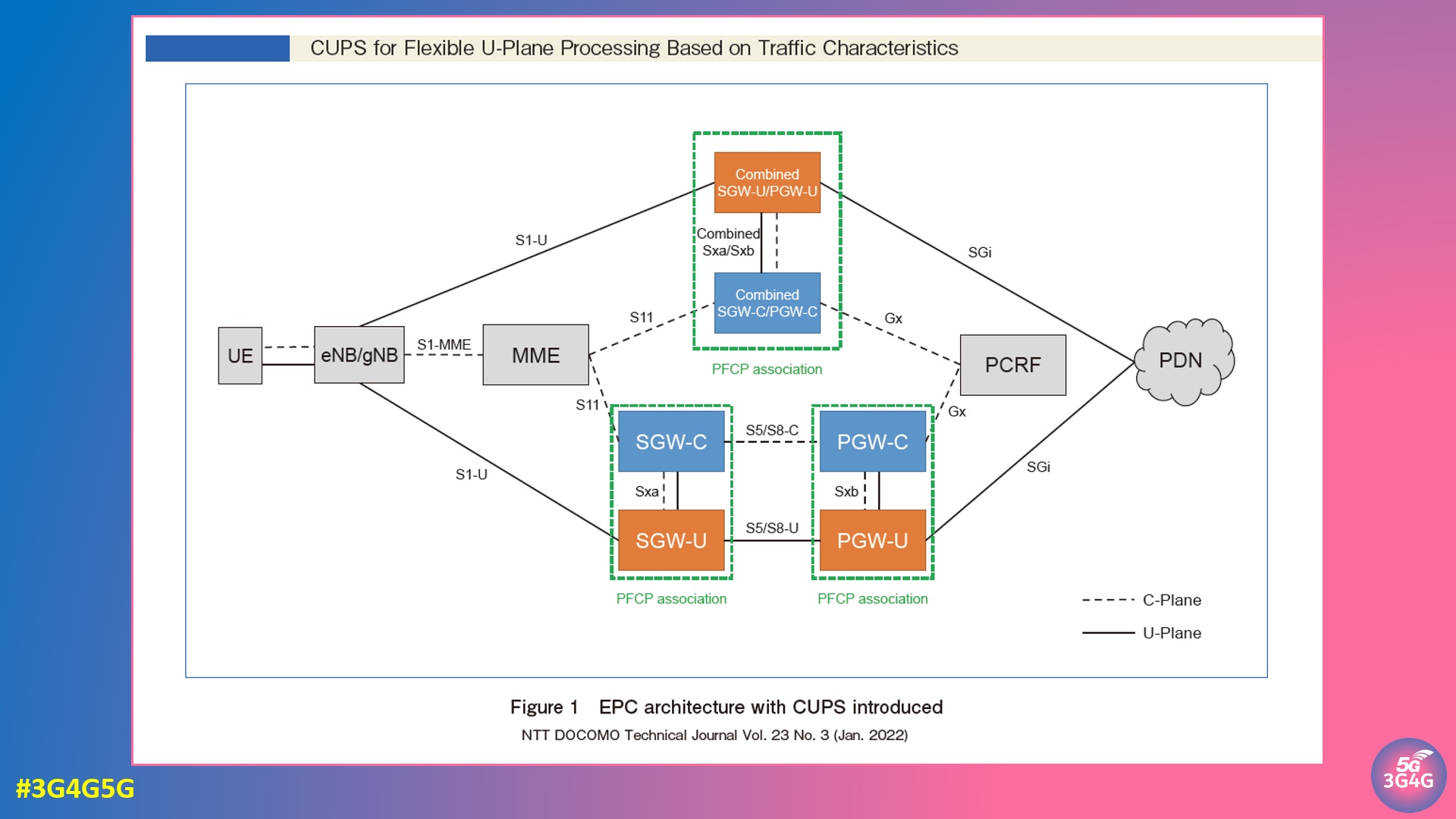
CUPS is an architecture defined in 3GPP TS 23.214 that separates the Serving GateWay (SGW)/Packet data network GateWay (PGW) configuration of the EPC into the C-Plane and U-Plane. The CUPS architecture is designed so that there is no difference in the interface between the existing architecture and the CUPS architecture - even with CUPS architecture deployed in SGW/PGW, opposing devices such as a Mobility Management Entity (MME), Policy and Charging Rules Function (PCRF), evolved NodeB (eNB)/ next generation NodeB (gNB), and SGWs/PGWs of other networks such as Mobile Virtual Network Operator (MVNO) and roaming are not affected. For C-Plane, SGW Control plane function (SGW-C)/PGW Control plane function (PGW-C), and for U-Plane, SGW User plane function (SGW- U)/PGW User plane function (PGW-U) are equipped with call processing functions. By introducing CUPS, C-Plane/U-Plane capacities can be expanded individually as needed. Combined SGW-C/PGW-C and Combined SGW-U/PGW-U can handle the functions of SGW and PGW in common devices. In the standard specification, in addition to SGW/PGW, the Traffic Detection Function (TDF) can also be separated into TDF-C and TDF-U, but the details are omitted in this article.

From above background, NTT DOCOMO has been planning to deploy Control and User Plane Separation (CUPS) architecture to realize the separation of C-Plane and U-Plane functions as specified in 3rd Generation Partnership Project Technical Specification (3GPP TS) 23.214. Separating the C-Plane and U-Plane functions of gateway devices with CUPS architecture makes it possible to scale the C-Plane and U-Plane independently and balance the centralized deployment of C-Plane functions with the distributed deployment of U- Plane functions, thereby enabling the deployment and development of a flexible and efficient core network. In addition to solving the aforementioned issues, CUPS will also enable independent equipment upgrades for C-Plane and U-Plane functions, and the adoption of U-Plane devices specialized for specific traffic characteristics.

In the user perspective, the introduction of CUPS can be expected to dramatically improve the user experience through the operation of facilities specializing in various requirements, and enable further increases in facilities and lower charges to pursue user benefits by improving the efficiency of core network facilities.

Regarding the CUPS architecture, a source of value for both operators and users, this article includes an overview of the architecture, additional control protocols, U-Plane control schemes based on traffic characteristics, and future developments toward a 5G Stand-Alone (5G SA) architecture.

The article is available here.

Related Posts

Monday 6 July 2020

A Technical Introduction to 5G NR RRC Inactive State


I looked at the RRC Inactive state back in 2017, but the standards were not completely defined. In the meantime standards have evolved and commercial 5G networks are rolling out left, right and centre. I made a short technical introduction to the RRC_INACTIVE state, comparing it with the 4G states in RRC and NAS. I also looked at some basic signalling examples and there are lots of relevant references at the end. Video and slides embedded below.


Related Posts:

Monday 18 December 2017

Control and User Plane Separation of EPC nodes (CUPS) in 3GPP Release-14


One of the items in 3GPP Rel-14 is Control and User Plane Separation of EPC nodes (CUPS). I have made a video explaining this concept that is embedded below.

In 3G networks (just considering PS domain), the SGSN and GGSN handles the control plane that is responsible for signalling as well as the user plane which is responsible for the user data. This is not a very efficient approach for deployment.

You can have networks that have a lot of signalling (remember signaling storm?) due to a lot of smartphone users but not necessarily consuming a lot of data (mainly due to price reasons). On the other hand you can have networks where there is not a lot of signalling but lot of data consumption. An example of this would be lots of data dongles or MiFi devices where users are also consuming a lot of data, because it’s cheap.

To cater for these different scenarios, the control plane and user plane was separated to an extent in the Evolved Packet Core (EPC). MME handles the control plane signalling while S-GW & P-GW handles the user plane

CUPS goes one step further by separating control & user plane from S-GW, P-GW & TDF. TDF is Traffic Detection Function which was introduced together with Sd reference point as means for traffic management in the Release 11. The Sd reference point is used for Deep Packet Inspections (DPI) purposes. TDF also provides the operators with the opportunity to capitalize on analytics for traffic optimization, charging and content manipulation and it works very closely with Policy and charging rules function, PCRF.

As mentioned, CUPS provides the architecture enhancements for the separation of S-GW, P-GW & TDF functionality in the EPC. This enables flexible network deployment and operation, by using either distributed or centralized deployment. It also allows independent scaling between control plane and user plane functions - while not affecting the functionality of the existing nodes subject to this split.

As the 3GPP article mentions, CUPS allows for:
  • Reducing Latency on application service, e.g. by selecting User plane nodes which are closer to the RAN or more appropriate for the intended UE usage type without increasing the number of control plane nodes.
  • Supporting Increase of Data Traffic, by enabling to add user plane nodes without changing the number of SGW-C, PGW-C and TDF-C in the network.
  • Locating and Scaling the CP and UP resources of the EPC nodes independently.
  • Independent evolution of the CP and UP functions.
  • Enabling Software Defined Networking to deliver user plane data more efficiently.

The following high-level principles were also adopted for the CUPS:
  • The CP function terminates the Control Plane protocols: GTP-C, Diameter (Gx, Gy, Gz).
  • A CP function can interface multiple UP functions, and a UP function can be shared by multiple CP functions.
  • An UE is served by a single SGW-CP but multiple SGW-UPs can be selected for different PDN connections. A user plane data packet may traverse multiple UP functions.
  • The CP function controls the processing of the packets in the UP function by provisioning a set of rules in Sx sessions, i.e. Packet Detection Rules for packets inspection, Forwarding Action Rules for packets handling (e.g. forward, duplicate, buffer, drop), Qos Enforcement Rules to enforce QoS policing on the packets, Usage Reporting Rules for measuring the traffic usage.
  • All the 3GPP features impacting the UP function (PCC, Charging, Lawful Interception, etc) are supported, while the UP function is designed as much as possible 3GPP agnostic. For example, the UPF is not aware of bearer concept.
  • Charging and Usage Monitoring are supported by instructing the UP function to measure and report traffic usage, using Usage Reporting Rule(s). No impact is expected to OFCS, OCS and the PCRF.
  • The CP or UP function is responsible for GTP-u F-TEID allocation.
  • A legacy SGW, PGW and TDF can be replaced by a split node without effecting connected legacy nodes.
CUPS forms the basis of EPC architecture evolution for Service-Based Architecture for 5G Core Networks. More in another post soon.

A short video on CUPS below, slides available here.


Further reading:


Sunday 22 May 2016

QCI Enhancements For Mission Critical Communications

Its been quite a while since I posted about QCI and end-to-end bearer QoS in EPC. In LTE Release-12 some new QCI values were added to handle mission critical communications.


This picture is taken from a new blog called Public Safety LTE. I have discussed about the Default and Dedicated bearers in an earlier post here (see comments in that post too). You will notice in the picture above that new QCI values 65, 66, 69 & 70 have been added. For mission critical group communications new default bearer 69 would be used for signalling and dedicated bearer 65 will be used for data. Mission critical data would also benefit by using QCI 70.


LTE for Public Safety that was published last year provides a good insight on this topic as follows:

The EPS provides IP connectivity between a UE and a packet data network external to the PLMN. This is referred to as PDN connectivity service. An EPS bearer uniquely identifies traffic flows that receive a common QoS treatment. It is the level of granularity for bearer level QoS control in the EPC/E-UTRAN. All traffic mapped to the same EPS bearer receives the same bearer level packet forwarding treatment. Providing different bearer level packet forwarding treatment requires separate EPS bearers.

An EPS bearer is referred to as a GBR bearer, if dedicated network resources related to a Guaranteed Bit Rate (GBR) are permanently allocated once the bearer is established or modified. Otherwise, an EPS bearer is referred to as a non-GBR bearer.

Each EPS bearer is associated with a QoS profile including the following data:
• QoS Class Identifier (QCI): A scalar pointing in the P-GW and eNodeB to node-specific parameters that control the bearer level packet forwarding treatment in this node.
• Allocation and Retention Priority (ARP): Contains information about the priority level, the pre-emption capability, and the pre-emption vulnerability. The primary purpose of the ARP is to decide whether a bearer establishment or modification request can be accepted or needs to be rejected due to resource limitations.
• GBR: The bit rate that can be expected to be provided by a GBR bearer.
• Maximum Bit Rate (MBR): Limits the bit rate that can be expected to be provided by a GBR bearer.

Following QoS parameters are applied to an aggregated set of EPS bearers and are part of user’s subscription data:
• APN Aggregate Maximum Bit Rate (APN-AMBR): Limits the aggregate bit rate that can be expected to be provided across all non-GBR bearers and across all PDN connections associated with the APN.
• UE Aggregate Maximum Bit Rate (UE-AMBR): Limits the aggregate bit rate that can be expected to be provided across all non-GBR bearers of a UE. The UE routes uplink packets to the different EPS bearers based on uplink packet filters assigned to the bearers while the P-GW routes downlink packets to the different EPS bearers based on downlink packet filters assigned to the bearers in the PDN connection.

Figure 1.5 above shows the nodes where QoS parameters are enforced in the EPS system.

Related links:


Sunday 4 October 2015

Updates from the 3GPP RAN 5G Workshop - Part 2

I have finally got round to having a look at some more presentations on 5G from the recently concluded 3GPP RAN 5G Workshop. Part 1 of the series is here.
Panasonic introduced this concept of Sub-RAT's and Cradle-RAT's. I think it should be obvious from the picture above what they mean but you can refer to their presentation here for more details.


Ericsson has provided a very detailed presentation (but I assume a lot of slides are backup slides, only for reference). They have introduced what they call as "NX" (No compatibility constraints). This is in line to what other vendors have referred to as well that above 6GHz, for efficiency, new frame structures and waveforms would serve best. Their slides are here.


Nokia's proposal is that in the phase 1 of 5G, the 5G Access point (or 5G NodeB) would connect to the 4G Evolved Packet Core (EPC). In phase 2, both the LTE and the 5G (e)NodeB's would connect to the 5G core. Their presentation is available here.

Before we move on to the next one, I should mention that I am aware of some research that is underway, mostly by universities where they are exploring an architecture without a centralised core. The core network functionality would be distributed and some of the important data would be cached on the edge. There will be challenges to solve regarding handovers and roaming; also privacy and security issues in the latter case.
I quite like the presentation by GM research about 5G in connected cars. They make a very valid point that "Smartphones and Vehicles are similar but not the same. The presentation is embedded below.


Qualcomm presented a very technical presentation as always, highlighting that they are thinking about various future scenarios. The picture above, about phasing is in a way similar to the Ericsson picture. It also highlights what we saw in part 1, that mmW will arrive after WRC-19, in R16. Full presentation here.


The final presentation we are looking is by Mitsubishi. Their focus is on Massive MIMO which may become a necessity at higher frequencies. As the frequency goes higher, the coverage goes down. To increase the coverage area, beamforming can be used. The more the antennas, the more focused the beam could be. They have also proposed the use of SC-FDMA in DL. Their presentation is here and also embedded below.


Saturday 1 November 2014

4G Security and EPC Threats for LTE

This one is from the LTE World Summit 2014. Even though I was not there for this, I think this has some useful information about the 4G/LTE Security. Presentation as follows:


Saturday 17 May 2014

NFV and SDN - Evolution Themes and Timelines


We recently held our first Virtual Networks SIG event in Cambridge Wireless. There were some great presentations. The one by the UK operator EE summarised everything quite well. For those who are not familiar with what NFV and SDN is, I would recommend watching the video on my earlier post here.

One of the term that keeps being thrown around is 'Orchestration'. While I think I understand what it means, there is no easy way to explain it. Here are some things I found on the web that may explain it:
Orchestration means Automation, Provisioning, Coordination and Management of Physical and Virtual resources.  
Intelligent service orchestration primarily involves the principles of SDN whereby switches, routers and applications at Layer 7 can be programmed from a centralized component called the controller with intelligent decisions regarding individual flow routing in real time.
If you can provide a better definition, please do so.
There are quite a few functions and services that can be virtualised and there are some ambitious timelines.

ETSI has been working on NFV and as I recently found out (see tweet below) there may be some 3GPP standardisation activity starting soon.
Anyway, here is the complete presentation by EE:


There was another brilliant presentation by Huawei but the substance was more in the talk, rather than the slides. The slides are here in case you want to see and download.

Related post:


Wednesday 27 February 2013

Wi-Fi & Packet Core (EPC) Integration

Yesterday I wrote a blog post on whether Wi-Fi is the third RAN in the Metrocells blog. Today I am posting this excellent presentation that details how this Wi-Fi integration with EPC will be done.


Sunday 8 July 2012

3GPP based 'Sponsored Data Connectivity'


One of the features being investigated and added is the Sponsored Data Connectivity feature in the Evolved Packet System. This feature has lots of backers as this is deemed to be a new source of revenue for the operators.

In Release-10 one of the items for this is titled 'Policy Enhancements for Sponsored Connectivity and Coherent Access to Policy related Databases (PEST)'

The justification for PEST is as follows:


With the emerging of innovative IP services, the transactional data usage is becoming more and more prevalent on the mobile. For example, the user downloads a purchased ebook from an online store; the user purchases and downloads a game from an operator store; the user views free trailer clip from an online library to determine whether to buy the entire movie or not. In many cases, the Sponsor (e.g., Application service provider) pays for the user’s data usage in order to allow the user to access the Application Service Provider’s services. This enables additional revenue opportunities for both the Application service providers and the operators.


In particular, such dynamic data usage provided by the Sponsor allows the operator to increase revenues from the users with limited data plans. The user may have limited data plans allowing only a nominal data volume per month and the Sponsor may dynamically sponsor additional volume for the user to allow access to the services offered by the Application service providers.


The PCC framework can be enhanced to enable such use cases, in particular, it allows the operator to provide service control based on such sponsored services. For example, it allows a dynamic IP flow to be excluded from the user’s data plan since a Sponsor might sponsor the data usage for the identified IP flows. For example, the user may use the limited data plan to browse an online store for interested books; but once a book is purchased, the data usage for downloading the book can be granted for free. In addition, the IP flow may also be granted certain level of QoS (e.g. video streaming).


TR 23.813 studied the feasibility of these scenarios of sponsored connectivity in the key issue 1 and converged into a set of extensions to the PCC procedures which will allow the operator to provide sponsored connectivity to sponsor entities.


In addition to Key Issue 1, SA2 also studied the feasibility of Key issue 2 - Coherent access to Policy related databases within TR 23.813. It enables UDR (User Data Repository) in the PCC architecture as an optional functional entity where PCC related subscriber data can be stored and retrieved by the PCRF through the Ud interface. This deployment scenario does not require SPR and allows the PCRF access to the PCC related subscriber data stored in the UDR.

In Release-12 PEST is linked to another new feature titled, 'Interworking between Mobile Operators using the Evolved Packet System and Data Application Providers (MOSAP)'

The Justification of this is as follows:


Mobile operators have to deal with increasing flexibility of data services delivery on different devices. 


The data services could be hosted by the mobile operators in their data centers within 3GPP domain or could be hosted by 3rd party data application providers that could be outside of the mobile operator domain. 


Current practices involve individual mobile operators negotiating agreements with data application providers resulting in proprietary additional functionalities in 3GPP networks which results in  non-standard 3GPP interfaces. With the advent of new models of services delivery like cloud computing and Application Stores, it is important that the mobile operator minimises upgrades to the network  and associated backend integration. 


Also the mobile operator has the opportunity to explore various charging models in this interworking scenario with data service providers. 


Sample services/capabilities that mobile operators can provide to data application providers are customised billing/charging, promotional services, group addressing capabilities, identity services, statistics, etc.


This WI proposes to enable the mobile operator to use enhanced functionalities and interfaces to meet the needs of the rapidly changing industry models. The WI is expected to develop requirements and architectural frameworks for authentication, authorization, policy, charging, mobility and session continuity aspects for various interworking scenarios.


The existing schemes for authentication/authorization and charging need to be studied and updated/enhanced, when deemed necessary, by liaising with other 3GPP Working Groups/SDOs/fora in charge of them.


This WI was de-prioritised in Rel-11. The Rel-12 work will take into consideration the new TS 23.682 developed in Rel-11 (Architecture Enhancements to facilitate communications with Packet Data Networks and Applications).

What are you your thoughts on sponsored data connectivity?

xoxoxoxoxoxo  Added on 08/07/2012 - 14.00 xoxoxoxoxoxo


I had a quick discussion with Dean Bubley on twitter and here is what he thinks:

Key question is what use cases & how the biz model / sponsor interaction works. 1-800 model is a #UselessCase for example. I think tollfree/1-800 apps is a nice idea, but totally unworkable when you drill into the practicalities. There are a few corner-cases & niche exceptions (eg govt-supplied apps) but proposed case for general apps / content is a chimera. 

More details on what Dean Bubley means is on his blog post here.

The comment at the end is very interesting, summarising the hurdles that exist in providing 'Toll-free data'.

My belief is that since the operators are running out of the options in generating new revenues, they may make a compromise and find a middle ground for making the 'Sponsored-data' to work

Thursday 7 June 2012

On Signalling Storm... #LTEWS


The Signalling Storm is coming, its not the question of 'if' but when. This was the unanimous message from the Signaling Focus Day of the 8th LTE World Summit 2012. Several high profile outages have been associated to the Signalling storm, NTT Docomo and Verizon being the main one. Luckily the Telenor outage was due to software issues.

The problem is divided into two parts, the Access network part where the Air Interface is the bottleneck and the core network part which can easily be swamped by the overwhelming amount of Signalling due to more intelligent billing system and always on devices with background applications generating much more amount of traffic as would have on an older system. Lets look at them in turn.

Core Network Signalling Storm:

As I reported earlier, Diameter has been highlighted as a way of salvation for the operators with dozens of use cases but due to its immaturity has caused outages and have given it a bad name. As Connected Planet mentions, "According to one signaling expert, launching the iPhone’s browser, for example, instantly sets off about fifteen individual network signaling requests. Beyond that, 4G network software elements supporting increasingly sophisticated mobile service scenarios “talk” to each other at rates that traditional TDM/SS7-based networks never had to deal with." Hopefully a stable implementation of Diameter protocol will help not only solve the signalling storm but will help generate new models for charging and revenue generation.

A presentation by Ed Gubbins of Current Analysis, comparing the big vendors of Diameter Signalling is available here.

Access Network Signalling Storm:

My thinking is that the Core Network Signalling problem will become an issue some years down the road whereas the Access Network Signalling problem will be seen sooner rather than later. In fact for 3G/HSPA the problem is becoming more visible as the market has matured and more and more users are moving towards using smartphones, Since LTE rollouts are in its infancy (in most markets) the problem is still some way away.

One of the reasons for Signalling storm is the incorrect APN name. I reported earlier about Telefonica's approach to solve this problem by using 'Parking APN', see here.

Also embedded below are couple of presentations from the Signalling Focus day that talk about the problem from Access Network point of view


Other Interesting Reading Material

Finally there is an excellent whitepaper from Heavy Reading titled "The Evolution of the Signalling Challenge in 3G & 4G networks", available here to download.

Another excellent article summarising the problem is from Huawei magazine available here.

Friday 11 May 2012

Updated LTE Architecture with LCS and MBMS entities

Here is an attempt to update the LTE Architecture with MBMS and Location Services (LCS) entities included


You can also refer to the following old posts:


Monday 26 March 2012

3GPP LTE Evolved Packet System & Application to Femtos

A video of the actual presentation is embedded below. Its quite long (94 minutes)


The presentation is available to download in PDF format from here.

Wednesday 14 December 2011

ETSI INT IMS/EPC Interoperability Standardisation: Motivation, Roadmap & First Results

INT = IMS Network Testing. ETSI INT website here. More details below the presentation:

This was presented by Giulio Maggiore, Telecom Italia, ETSI TC INT Chairman in the 2nd FOKUS FUSECO Forum 2011, Berlin 17-18 Nov. 2011

From the ETSI leaflet (note that this is quite old information but still on the ETSI website here):

IMS interoperability is a key issue for boosting IMS (IP Multimedia Subsystem) roll-out and more specifically network interconnection between operators. Only through thorough testing in practical scenarios can operators ensure operational excellence in a multi-vendor and multi-provider environment.


IMS comprises a set of specifications designed to enable network operators to implement IP-based networks that can carry services for both fixed and mobile customers simultaneously.


IMS was developed originally in the mobile world (specifically in the specifications created by the 3rd Generation Partnership Project, 3GPP), and was adopted for fixed networks by ETSI’s TISPAN Technical Committee (Telecoms & Internet Converged Services & Protocols for Advanced Networks).


However this promise of advanced communications over the next generation network will only be delivered if those same networks can interconnect.


ETSI’s Technical Committee INT: IMS Network Testing


ETSI is bridging the existing gap between 3GPP IMS Core Network standards and the initial industry IMS implementations through the organization of IMS interoperability events in connection with ETSI’s Centre for Testing & Interoperability (CTI) and Plugtests™ interoperability testing service.


Our Technical Committee for IMS Network Testing (TC INT) is actively establishing close contact with a number of industry fora and organizations dealing with IMS interoperability, including 3GPP, GSMA, MSF (Multi Service Forum), IMS Forum and the ITU-T. TC INT develops IMS test specification according to conformance, network integration and interoperability testing methodologies. Other ongoing work includes development of tests for Supplementary Services based on regulatory requirements and IMS tests with legacy networks (e.g. SIP-I).


ETSI has already held two IMS interoperability events. The first examined interconnection aspects of 3GPP IMS Release 6, including such issues as basic call on the Mw interface. The second event had a wider scope that included the testing of 3GPP IMS Release 7 interworking, roaming, border control, and integration of application servers executing selected Multimedia Telephony supplementary services.


Future ETSI activities and events will go even deeper towards bridging 3GPP IMS standards and industry implementations. These will include the organization of further IMS interoperability events designed to boost the roll-out and take-off of IMS services and operators’ network interconnections.

Tuesday 19 April 2011

Unstructured Supplementary Service Data (USSD) simulation service in IMS (USSI)

I hope we all know USSD. If not then hopefully my old blog post will help remind you of USSD. Apparently USSD is as popular as it was nearly a decade back since it is supported by 100% of the phones. As a result 3GPP have made sure that a USSD like service is available in LTE/SAE since USSD was designed for a CS domain and in SAE we have only the PS domain.


Picture Source: Aayush Weblog

The following is from the 3GPP document:

Today mobile initiated unstructured SS data in MMI mode are widely used to interact with proprietary home-network provided services, e.g. to activate or deactivate certain features or to interrogate some parameter settings.

The user dials a certain feature code, e.g. in the format “*# ”, this code is forwarded to the home network and answered with a text string providing the requested information. Unlike common SMS the string is displayed immediately and not stored on the UE.

A typical use case is the interrogation of the account balance in a prepaid service. The prepaid user e.g. dials "*101#", the message is forwarded to the HPLMN and further to the IN system where the account balance is checked and finally the current value is transferred to the user in a short answer string, e.g. "Balance: € 35,40". Another use case is controlling the active UE for incoming calls and messages in case of a hunting service / multi SIM service.

From a network perspective the functionality is as follows:
1. The user sends the request
2. USSD is sent as MAP message to the HPLMN
3. USSD is forwarded to a Service Node (SN) [non-standardized functionality]
4. USSD is answered
5. answer
6. answer

The mentioned functionality is not available in the EPS. So e.g. a business customer who is subscribed to a certain multi SIM service will use his UEs via CS and EPS/IMS. Dependent on the access he would have to use different mechanisms for controlling the active UE.

This problem can be avoided when introducing completely new services. Then mechanisms can be used that are available via all access networks, e.g. web interfaces via GPRS or EPS. However we are talking about existing services with a broad customer base that is accustomed to use USSD codes as they are fast and simple to use.

As USSD is widely used in CS domain, operators would benefit from re-using the already deployed servers also when the user accesses services that make use of USSD over IMS.

It is therefore desirable to create in 3GPP a service which provides the same capabilities for the user, like the well known "GSM Mobile User Initiated USSD" feature.

For the user, it is important that the user experience is transparent (I.e. the look and feel of the service is independent of the transport mechanism used to convey the USSD payload to the network).


Possible solutions

There are several possibilities to solve this issue. One would be to re-introduce USSD in EPS. This is not the intention as it creates too much overhead. The idea is to specify a light weight solution which provides the same look and feel for the user but uses existing network mechanisms, i.e. only to simulate the USSD service.

One variant could be that the UE when being attached via the EPS to the IMS encapsulates the USSD codes in IP messages and forwards them to the network. This could happen either via the Ut interface as XCAP data using http or in a SIP message.

It should be noted that there are also user initiated MMI mode USSDs for VPLMN use. The differentiation, if USSD are intended for HPLMN or VPLMN use, is done via the range of the feature code. If USSD for VPLMN use were to be supported / simulated this may prevent certain solutions (e.g. using the Ut) and have some architectural impact (considering all possible roaming scenarios for the IMS).

Proposal

To specify an easy solution having no architectural impact. Only the simulation of mobile initiated USSD – MMI mode for HPLMN use should be supported. The functionality should be available for Multimedia Telephony, i.e. it can be implemented with the MMTel UE client and USSD messages are sent to and answered by the MMTel AS.


Though there isn't much details on this feature available, Ayush's weblog has some more details on this feature here.