Saturday, 10 September 2022

CUPS for Flexible U-Plane Processing Based on Traffic Characteristics

I looked at Control and User Plane Separation (CUPS) in a tutorial, nearly five years back here. Since then most focus has been on 5G, not just on my blogs but also from the industry. 

Earlier this year, NTT Docomo's Technical Journal looked at CUPS for Flexible U-Plane Processing Based on Traffic Characteristics. The following is an extract from the article:

At the initial deployment phase of 5th Generation mobile communication systems (5G), the 5G Non-Stand-Alone (NSA) architecture was widely adopted to realize 5G services by connecting 5G base stations to the existing Evolved Packet Core (EPC). As applications based on 5G become more widespread, the need for EPC to achieve higher speed and capacity communications, lower latency communications and simultaneous connection of many terminals than ever has become urgent. Specifically, it is necessary to increase the number of high-capacity gateway devices capable of processing hundreds of Gbps to several Tbps to achieve high-speed, high-capacity communications, to distribute gateway devices near base station facilities to achieve even lower latency communications, and to improve session processing performance for connecting massive numbers of terminals simultaneously.

Conventional single gateway devices have both Control Plane (C-Plane) functions to manage communication sessions and control communications, and User Plane (U-Plane) functions to handle communications traffic. Therefore, if the previously assumed balance between the number of sessions and communications capacity is disrupted, either the C-Plane or the U-Plane will have excess processing capacity. In high-speed, high-capacity communications, the C-Plane has excess processing power, and in multiple terminal simultaneous connections, the U-Plane has excess processing power because the volume of communications is small compared to the number of sessions. If the C-Plane and U-Plane can be scaled independently, these issues can be resolved, and efficient facility design can be expected. In addition, low-latency communications require distributed deployment of the U-Plane function near the base station facilities to reduce propagation delay. However, in the distributed deployment of conventional devices with integrated C-Plane and U-Plane functions, the number of sessions and communication volume are unevenly distributed among the gateway devices, resulting in a decrease in the efficiency of facility utilization. Since there is no need for distributed deployment of C-Plane functions, if the C-Plane and U-Plane functions can be separated and the way they are deployed changed according to their characteristics, the loss of facility utilization efficiency related to C-Plane processing capacity could be greatly reduced.

CUPS is an architecture defined in 3GPP TS 23.214 that separates the Serving GateWay (SGW)/Packet data network GateWay (PGW) configuration of the EPC into the C-Plane and U-Plane. The CUPS architecture is designed so that there is no difference in the interface between the existing architecture and the CUPS architecture - even with CUPS architecture deployed in SGW/PGW, opposing devices such as a Mobility Management Entity (MME), Policy and Charging Rules Function (PCRF), evolved NodeB (eNB)/ next generation NodeB (gNB), and SGWs/PGWs of other networks such as Mobile Virtual Network Operator (MVNO) and roaming are not affected. For C-Plane, SGW Control plane function (SGW-C)/PGW Control plane function (PGW-C), and for U-Plane, SGW User plane function (SGW- U)/PGW User plane function (PGW-U) are equipped with call processing functions. By introducing CUPS, C-Plane/U-Plane capacities can be expanded individually as needed. Combined SGW-C/PGW-C and Combined SGW-U/PGW-U can handle the functions of SGW and PGW in common devices. In the standard specification, in addition to SGW/PGW, the Traffic Detection Function (TDF) can also be separated into TDF-C and TDF-U, but the details are omitted in this article.

From above background, NTT DOCOMO has been planning to deploy Control and User Plane Separation (CUPS) architecture to realize the separation of C-Plane and U-Plane functions as specified in 3rd Generation Partnership Project Technical Specification (3GPP TS) 23.214. Separating the C-Plane and U-Plane functions of gateway devices with CUPS architecture makes it possible to scale the C-Plane and U-Plane independently and balance the centralized deployment of C-Plane functions with the distributed deployment of U- Plane functions, thereby enabling the deployment and development of a flexible and efficient core network. In addition to solving the aforementioned issues, CUPS will also enable independent equipment upgrades for C-Plane and U-Plane functions, and the adoption of U-Plane devices specialized for specific traffic characteristics.

In the user perspective, the introduction of CUPS can be expected to dramatically improve the user experience through the operation of facilities specializing in various requirements, and enable further increases in facilities and lower charges to pursue user benefits by improving the efficiency of core network facilities.

Regarding the CUPS architecture, a source of value for both operators and users, this article includes an overview of the architecture, additional control protocols, U-Plane control schemes based on traffic characteristics, and future developments toward a 5G Stand-Alone (5G SA) architecture.

The article is available here.

Related Posts

Friday, 26 August 2022

How Multiband-Cells are used for MORAN RAN Sharing

In the previous blog post I have explained the concept of multi-band cells in LTE networks and promised to explain a bit deeper how such cells can be used in Multi-Operator RAN (MORAN) scenarios. 

MORAN is characterized by the fact that all network resources except the radio carriers and the Home Subscriber Server (HSS) are shared between two or more operators. 

What this means in detail can be see in Step 1 of the figure below. 

The yellow Band #1 spectrum of the multi-band cell is owned by Network Operator 1 while the blue spectrum of Band #2 and Band #3 belongs to Network Operator 2.

Band #1 is the default band. This means if a UE enters the cell is always has to establish the initial RRC signaling connection on Band #1 as shown in step 1.

The spectrum owned by Network Operator 2 comes into the game as soon as a dedicated radio bearer (DRB), in the core network known as E-RAB, is established in this RRC connection. 

Then we see intra-frequency (intra-cell) handover to Band #2 where the RRC signaling connection is continued. Band #3 is added for user plane transport as a secondary "cell" (the term refers to the 3GPP 36.331 RRC specification). 

The reason for this behavior can be explained when looking a frequency bandwidths. 

The default Band #1 is a low frequency band with a quite small bandwidth, e.g. 5 MHz. as it is typically used for providing good coverage in rural areas. Band #2 is also a lower frequency band, but Band #3 is a high frequency band with maximum bandwidth of 20 MHz. So Band #3 brings the highest capacity for user plane transport and that is the reason for the handover to the spectrum owned by Network Operator 2 and the carrier aggregation used on these frequency bands. 

However, due to the higher frequency the footprint of Band #3 is lower compared to the other two frequency bands. 

For UEs at the cell edge (or located in buildings while being served from the outdoor cell) this leads quite often to situations where the radio coverage of Band #3 becomes insufficient. In such cases the UE typically sends a RRC measurement event A2 (means: "The RSRP of the cell is below a certain threshold."). 

If such A2 event is received by the eNB it stops the carrier aggregation transport and releases the Band #3 resources so that all user plane transport continues to run on the limited Band #2 resources as shown in step 3.

And now in the particular eNB I observed a nice algorithm starts that could be seen as a kind of zero-touch network operation although it does not need big data nor artificial intelligence. 

10 seconds after the secondary frequency resources of Band #3 have been deleted they are added again to the connection, but if the UE is still at the same location the next A2 will be reported soon and carrier aggregation will be stopped again for 10 seconds and then the next cycle starts.

This automation loop is carried out endlessly until the UE changes its location or the RRC connection is terminated. 

Related Posts:

Monday, 22 August 2022

DCCA Features and Enhancements in 5G New Radio

In another new whitepaper on 5G-Advanced, Nokia has detailed DCCA (DC + CA) features and enhancements from Rel-15 until Rel-18. The following is an extract from the paper:

Mobility is one of the essential components of 5G-Advanced. 3GPP has already defined a set of functionalities and features that will be a part of the 5G-Advanced Release 18 package. These functionalities can be grouped into four areas: providing new levels of experience, network extension into new areas, mobile network expansion beyond connectivity, and providing operational support excellence. Mobility enhancements in Release 18 will be an important part of the ‘Experience enhancements” block of features, with the goal of reducing interruption time and improving mobility robustness.

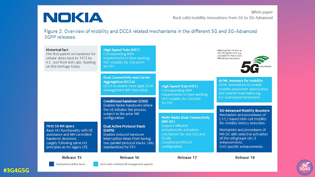
Fig. 2 shows a high-level schematic of mobility and dual connectivity (DC)/Carrier Aggregation (CA) related mechanisms that are introduced in the different 5G legacy releases towards 5G-Advanced in Release 18. Innovations such as Conditional Handover (CHO) and dual active protocol stack (DAPS) are introduced in Release 16. More efficient operation of carrier aggregation (CA), dual connectivity (DC), and the combination of those denoted as DCCA, as well as Multi-Radio Access Technology DC (MR-DC) are introduced through Releases 16 and 17.

For harvesting the full benefits of CA/DC techniques, it is important to have an agile framework where secondary cell(s) are timely identified and configured to the UE when needed. This is of importance for non-standalone (NSA) deployments where a carrier on NR should be quickly configured and activated to take advantage of 5G. Similarly, it is of importance for standalone (SA) cases where e.g. a UE with its Primary Cell (PCell) on NR Frequency Range 1 (FR1) wants to take additional carriers, either on FR1 and/or FR2 bands, into use. Thus, there is a need to support cases where the aggregated carriers are either from the same or difference sites. The management of such additional carriers for a UE shall be highly agile in line with the user traffic and QoS demands; quickly enabling usage of additional carriers when needed and again quickly released when no longer demanded to avoid unnecessary processing at the UE and to reduce its energy consumption. This is of particular importance for users with time-varying traffic demands (aka burst traffic conditions).

In the following, we describe how such carrier management is gradually improved by introducing enhancements for cell identification, RRM measurements and reduced reporting delays from UEs. As well as innovations related to Conditional PSCell Addition and Change (CPAC) and deactivation of secondary cell groups are outlined.

The paper goes on to discuss the following scenarios in detail for DCCA enhancements:

  • Early measurement reporting
  • Secondary cell (SCell) activation time improvements
    • Direct SCell activation
    • Temporary RS (TRS)-based SCell Activation
  • Conditional Secondary Node (SN) addition and change for fast access
  • Activation of secondary cell group

The table below summarizes the DCCA features in 5G NR

Related Posts

Tuesday, 16 August 2022

Managing 5G Signalling Storms with Service Communication Proxy (SCP)

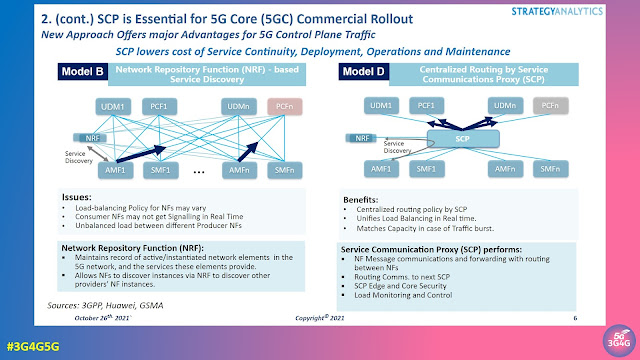
When we made our 5G Service Based Architecture (SBA) tutorial some four years back, it was based on Release-15 of the 3GPP standards. All Network Functions (NFs) simply sent discovery requests to the Network Repository Function (NRF). While this works great for trials and small scale deployments it can also lead to issues as can be seen in the slide above.

In 3GPP Release-16 the Service Communication Proxy (SCP) has now been introduced to allow the Control Plane network to handle and prioritize massive numbers of requests in real time. The SCP becomes the control point that mediates all Signalling and Control Plane messages in the network core.

SCP routing directs the flow of millions of simultaneous 5G function requests and responses for network slicing, microservice instantiation or edge compute access. It also plays a critical role in optimizing floods of discovery requests to the NRF and in overall Control Plane load balancing, traffic prioritization and message management.

A detailed whitepaper on '5G Signaling and Control Plane Traffic Depends on Service Communications Proxy (SCP)' by Strategy Analytics is available on Huawei's website here. This report was a follow on from the 'Signaling — The Critical Nerve Center of 5G Networks' webinar here.

Related Posts:

Wednesday, 10 August 2022

AI/ML Enhancements in 5G-Advanced for Intelligent Network Automation

Artificial Intelligence (AI) and Machine Learning (ML) has been touted to automate the network and simplify the identification and debug of issues that will arise with increasing network complexity. For this reason 3GPP has many different features that are already present in Release-17 but are expected to evolve further in Release-18. 

I have already covered some of this topics in earlier posts. Ericsson's recent whitepaper '5G Advanced: Evolution towards 6G' also has a good summary on this topic. Here is an extract from that:

Intelligent network automation

With increasing complexity in network design, for example, many different deployment and usage options, conventional approaches will not be able to provide swift solutions in many cases. It is well understood that manually reconfiguring cellular communications systems could be inefficient and costly.

Artificial intelligence (AI) and machine learning (ML) have the capability to solve complex and unstructured network problems by using a large amount of data collected from wireless networks. Thus, there has been a lot of attention lately on utilizing AI/ML-based solutions to improve network performance and hence providing avenues for inserting intelligence in network operations.

AI model design, optimization, and life-cycle management rely heavily on data. A wireless network can collect a large amount of data as part of its normal operations. This provides a good base for designing intelligent network solutions. 5G Advanced addresses how to optimize the standardized interfaces for data collection while leaving the automation functionality, for example, training and inference up to the proprietary implementation to support full flexibility in the automation of the network.

AI/ML for RAN enhancements

Three use cases have been identified in the Release 17 study item related to RAN performance enhancement by using AI/ML techniques. Selected use cases from the Release 17 technical report will be taken into the normative phase in the next releases. The selected use cases are: 1) network energy saving; 2) load balancing; and 3) mobility optimization.

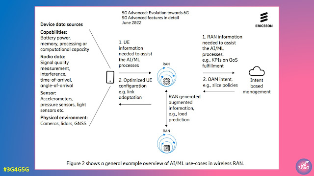
The selected use cases can be supported by enhancements to current NR interfaces, targeting performance improvements using AI/ML functionality in the RAN while maintaining the 5G NR architecture. One of the goals is to ensure vendor incentives in terms of innovation and competitiveness by keeping the AI model implementation specific. As shown in Fig.2 (on the top) an intent-based management approach can be adopted for use cases involving RAN-OAM interactions. The intent will be received by the RAN. The RAN will need to understand the intent and trigger certain functionalities as a result.

AI/ML for physical layer enhancements

It is generally expected that AI/ML functionality can be used to improve the radio performance and/or reduced the complexity/overhead of the radio interface. 3GPP TSG RAN has selected three use cases to study the potential air interface performance improvements through AI/ML techniques, such as beam management, channel state information feedback enhancement, and positioning accuracy enhancements for different scenarios. The AI/ML-based methods may provide benefits compared to traditional methods in the radio interface. The challenge will be to define a unified AI/ML framework for the air interface by adequate AI/ML model characterization using various levels of collaboration between gNB and UE.

AI/ML in 5G core

5G Advanced will provide further enhancements of the architecture for analytics and on ML model life-cycle management, for example, to improve correctness of the models. The advancements in the architecture for analytics and data collection serve as a good foundation for AI/ML-based use cases within the different network functions (NFs). Additional use cases will be studied where NFs make use of analytics with the target to support in their decision making, for example, network data analytics functions (NWDAF)- assisted generation of UE policy for network slicing.

If you are interested in studying this topic further, check out 3GPP TR 37.817: Study on enhancement for data collection for NR and ENDC. Download the latest version from here.

Related Posts

Tuesday, 2 August 2022

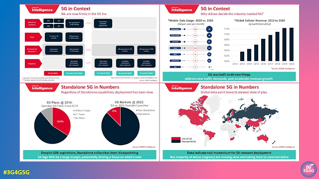
GSMAi Webinar: Is the Industry Moving Fast Enough on Standalone 5G?

I recently participated in a webinar, discussing one of my favourite topics, 5G Standalone (5G SA). If you do not know about 5G SA, you may want to quickly watch my short and simple video on the topic here.

Last year I blogged about GSA's 5G Standalone webinar here. That time we were discussing why 5G SA is taking time to deliver, it was sort of a similar story this time. Things are changing though and you will see a lot more of these standalone networks later this year and even early next year. 

The slides of the webinar are available here and the video is embedded below:

Here are some of my thoughts on why 5G SA is taking much longer than most people anticipated:

  • 5G SA will force operators to move to 5G core which is a completely new architecture. The transition to this is taking much longer than expected, especially if there are a lot of legacy services that needs to be supported.
  • Many operators are moving towards converged core with 4G & 5G support to simply the core. This transition is taking long.
  • For taking complete advantage of 5G architecture, cloud native implementation is required. Some operators have already started the transition to cloud native but others are lagging.
  • 5G SA speeds will be lower than NSA speeds hence some operators who don't have a lot of mid-band spectrum are delaying their 5G SA rollouts.
  • Many operators have managed to reduce their latency as they start to move to edge datacentres, hence the urgency for 5G standalone has reduced.
  • Most operators do not see any new revenue opportunities because of 5G SA, hence they want to be completely ready before rolling out 5G SA
  • Finally, you may hear a lot about not enough devices supporting 5G SA but that's not the device manufacturers views.  See this tweet from GSA ðŸ‘‡

Do you agree with my reasoning? If not, please let me know in the comments.

Related Posts

Monday, 25 July 2022

Demystifying and Defining the Metaverse

There is no shortage of Metaverse papers and articles as it is the latest trend in the long list of technologies promising to change the world. Couple of months back I wrote a post about it in the 6G blog here.

IEEE hosted a Metaverse Congress with the Kickoff Session 'Demystifying and Defining the Metaverse' this month as can be seen in the Tweet above. The video embedded below covers the following talks:

  • 0:01:24 - Opening Remarks by Eva Kaili (Vice President, European Parliament)
  • 0:09:51 - Keynote - Metaverse Landscape and Outlook by Yu Yuan (President-Elect, IEEE Standards Association)
  • 0:29:30 - Keynote - Through the Store Window by Thomas Furness (“Grandfather of Virtual Reality”)
  • 0:52:30 - Keynote - XR: The origin of the Metaverse as Water-Human-Computer Interaction (WaterHCI) by Steve Mann (“Father of Wearable Computing”)
  • 1:22:17 - Keynote - A Vision of the Metaverse: AI Infused, Physically Accurate Virtual Worlds by Rev Lebaredian (VP of Omniverse & Simulation Technology, NVIDIA)

Some fantastic definitions, explanations, use cases and vision on Metaverse. The final speaker nicely summarised Metaverse as shown in this slide below.

Worth highlighting point 6 that the Metaverse is device independent. I argued about something similar when we try and link everything to 6G (like we linked everything to 5G before). We are just in the beginning phase, a lot of updates and clarifications will come in the next few years before Metaverse starts taking a final shape.

Related Posts

Monday, 18 July 2022

APT 600 MHz Band Gets Approval from 3GPP

The current 600 MHz 5G band (n71) is getting an extension as 3GPP approves plan for APT 600 MHz band. Back in April, the 29th meeting of the APT Wireless Group (AWG-29) organized by the Asia Pacific Telecommunity (APT) concluded with the final approval of the new APT 600 MHz band plan that hoped to open an additional 40+40 MHz prime UHF spectrum. A similar approach back in 2013 resulted in the 45+45 MHz in the 700 MHz band, known in 3GPP as n28.

3GPP TSG RAN 96 (all docs here) approved a new work item to standardize the APT 600 MHz band plan which was initially proposed by the ITU-APT Foundation of India (IAFI).

RP-221778 (revision of RP-221062), provides a detailed justification for this new band. Quoting from the document:

The 470-694 MHz frequency range is allocated to the broadcasting service and mobile service on a co-primary basis in ITU Region 3. The frequency band 470-698 MHz, or parts thereof, was identified by WRC-15 in 7 countries in Region 3 through new footnote No. 5.296A for use by those administrations as listed wishing to implement terrestrial IMT systems. In addition, there is interest from other significant markets to do the same. Elsewhere, USA, Mexico and several other countries in ITU Region 2 also identified this band for IMT through footnotes 5.295 and 5.308A. It is noted that resolves 2 of revised Resolution 224 (Rev.WRC-19) to encourage administrations to take into account results of the existing relevant ITU Radio communication Sector studies, when implementing IMT applications/systems in the frequency bands 694-862 MHz in Region 1, in the frequency band 470-806 MHz in Region 2, in the frequency band 790-862 MHz in Region 3, in the frequency band 470-698 MHz, or portions thereof, for those administrations mentioned in No. 5.296A, and in the frequency band 698 790 MHz, or portions thereof, for those administrations mentioned in No. 5.313A.

Spectrum below 1 GHz is expectedly well suited for mobile broadband applications.  In particular, the unique propagation characteristics of the bands below 1 GHz allow for wider area coverage, which in turn requires fewer infrastructures and facilitates service delivery to rural or sparsely populated areas. In this regard, the 700MHz ecosystem is growing swiftly: there are over 34 commercial networks deployments.  The APT700 band plan coming out from Region 3 played a huge role in its success globally. Outside of APAC, countries in Region 2 have adopted or plan to adopt the APT700 band plan (3GPP band 28) for LTE system deployments. The lower duplexer of APT700 plan has also been adopted for Region 1 since the conclusion of WRC-15.

As the utilisation of the 700MHz spectrum increases over time, it is desirable to look at additional spectrum that could be considered as a companion besides 3GPP Band 28. Therefore, the use of parts of the 600MHz band for the mobile broadband service would provide a vital means of delivering high quality, wide area broadband services including in rural areas and deep inside buildings. The timely availability of frequency arrangements is essential for the development of IMT specifications and standards and the early consideration by Administrations in the footnotes referred to above of suitable frequency arrangements. 

The APT region is very diverse and consists of highly developed and developing countries and some with extremely large and rural population base. The sub 1 GHz bands is well suited for the later.

During the last year or so, 3GPP RAN 4 has completed a study item on the feasibility of various duplex filter options for use in this band. The results of this study are documented in TR 38.860. This study was sent to the AWG in an LS RP-212629 in Sep 2021 with a request to provide guidance on a preferred band plan and information on regulatory aspects for the normative work to begin. The AWG 28 meeting has considered the request of the 3GPP and has provided a response to this LS. In this response the LS has indicated a preference for option B1 (full band) and has also requested for the work to begin immediately with a view to completion by Dec 2022. Additionally, the answers to the regulatory questions sought by the 3GPP have now been provided via a reply LS RP 221045.

The band plan for the option B1 that has a single duplexer or full band- is shown in Table 1 below.

The Tx-Rx is "reverse-duplex"; in other words, the downlink frequency band is below the duplex gap while the uplink frequency band is above the duplex gap. This arrangement is opposite to conventional notation; however, for this band, it provides the benefit of aligning the uplink band adjacent to 3GPP band 28 thereby minimizing interference conditions at the 703 MHz boundary.

Accordingly, the companies listed here request 3GPP to start normative work on the following option. 

  • Option B1 with a single duplexer 

For anyone interested in studying this further might want to refer to 3GPP TR 38.860: Study on Extended 600 MHz NR band.

Related Posts

Tuesday, 5 July 2022

5G and Cyber Security

Dr. Seppo Virtanen is an Associate Professor in Cyber Security Engineering and Vice Head of Department of Computing, the University of Turku, Finland. At 5G Hack The Mall 2022, he presented a talk on Cybersecurity and 5G. 

In the talk he covered the following topics:

  • Cybersecurity and Information Security
  • The CIA (Confidentiality, Integrity and Availability) Model
    • Achieving the goals of the CIA model
  • Intrusion and Detection
    • Intrusion detection, mitigation and aftercare
  • Smart Environments
    • Abstraction levels
    • Cybersecurity in smart environments
    • Cyber security concerns in smart environments
    • Security concerns in Smart Personal Spaces
    • Security concerns in Smart Rooms and Buildings
    • Security concerns of a participant in a smart environment
    • Cyber Security Concerns in Smart Environments
  • Cyber Security in the 5G context
  • Drivers for 5G security
  • Securing 5G

This video embedded below is a nice introduction to cybersecurity and how it overlaps with 5G:

Related Posts:

Tuesday, 28 June 2022

3GPP Explains TSG CT Work on UAS Connectivity, Identification and Tracking

Drones, technically Unmanned Aerial Vehicles/Systems or UAVs/UASs, have been a subject of interest for a very long time due to the wide variety of use cases they can offer. In the recent issue of 3GPP Highlights newsletter, Lena Chaponniere, 3GPP Working Group CT1 Vice-Chair has written an article about TSG CT work on UAS Connectivity, Identification and Tracking. Interestingly, the 3GPP abbreviation for UAS is slightly different, Uncrewed Aerial Systems.

Quoting from the newsletter: 

One of the defining drivers of 5G is the expansion beyond traditional mobile broadband to provide solutions meeting the needs of vertical industries.

A very good example of 3GPP rising up to this challenge is the work done in Release 17 to use cellular connectivity to support Uncrewed Aerial Systems (UAS), thereby enabling this vertical to benefit from the ubiquitous coverage, high reliability, QoS, robust security, and seamless mobility provided by the 3GPP system.

A key component of this work took place in CT Working Groups, which under the leadership of Sunghoon Kim (CT Work Item rapporteur) and Waqar Zia (rapporteur of new specifications TS 29.255 and TS 29.256) developed the necessary protocols and APIs to meet the service requirements specified in 3GPP SA1 and the architectural enhancements specified in 3GPP SA2, as part of the Release 17 Work Item on ‘ID_UAS’.

The key functions of the 3GPP architecture for ID_UAS are depicted in the following figure:

The work in CT Working Groups focused on specifying support for the following features:

UAV remote identification: The CAA (Civil Aviation Administration)-Level UAV ID was introduced in the 3GPP system. It is a globally unique, electronically and physically readable, and tamper resistant identification which allows the receiving entity to address the correct USS for retrieval of UAV information and can be assigned solely by the USS, via means outside the scope of 3GPP, or assigned by the USS with assistance from 3GPP system, whereby the USS delegates the role of “resolver” of the CAA-Level UAV ID to the UAS NF.

AV USS authentication and authorization (UUAA): The first step for the owner of the UAV is to register the UAV with the USS, via a procedure outside the scope of 3GPP, which can take place offline or using internet connectivity. During this procedure, the CAA-level UAV ID is configured in the UAV and the aviationlevel information (e.g. UAV serial number, pilot information, UAS operator, etc.) is provided to the USS.

The UE at the UAV then registers with the 3GPP system by using existing procedures for 3GPP primary authentication, with the MNO credentials stored in the USIM.

After successful authentication of the UE, the UUAA procedure is performed, to enable the 3GPP Core Network to verify that the UAV has successfully registered with the USS. In 5GS, this procedure can take place during the 3GPP registration, or during the establishment of a PDU session for UAS services.

For the former, CT1 extended the registration procedure in TS 24.501 to enable the UE to indicate its CAA-Level UAV ID into a new container (Service-level-AA container) included in the Registration Request message, which triggers the AMF to initiate UUAA with the USS by invoking the Nnef_Authentication service toward the UAS NF, as specified by CT4 in new specification TS 29.256, and the UAS NF to invoke the Naf_Authentication service toward the USS, as specified by CT3 in new specification TS 29.255.

For the latter, CT1 extended the PDU session establishment procedure in TS 24.501 to enable the UE to indicate its CAA-Level UAV ID via the Service-level-AA container included in the PDU Session Establishment Request message, which triggers the SMF to initiate UUAA with the USS via the UAS NF by invoking the services mentioned above. In order to enable exchanging the authentication messages between the UE and the USS, CT1 specified a new Session Management procedure in TS 24.501, in which the SMF sends a Service-level Authentication Command to the UE in a Downlink NAS Transport message. The UE replies to this command with a Service-level Authentication Complete carried in an Uplink NAS Transport message. In EPS, the UUAA procedure takes place during PDN connection establishment, and the information exchanged to that end between the UAV and the PGW is carried in the Service-level-AA container included in the ePCO

C2 communication over cellular connectivity: C2 communication over cellular connectivity consists of the UAV establishing a user plane connection to receive C2 messages from a UAVC, or to report telemetry data to a UAVC. Authorization for C2 communication by the USS is required and includes authorization for pairing of the UAV with a UAVC, as well as flight authorization for the UAV.

C2 communication authorization may be performed:

  • during the UUAA procedure (if UUAA is carried out at PDU session/PDN connection establishment) when the UAV requests establishment of a PDU Session/PDN connection for both UAS services and C2 communication
  • during PDU session modification/UE requested bearer resource modification when the UAV requests to use an existing PDU session/PDN connection for C2 communication
  • during a new PDU session/PDN connection establishment, if the UAV requests to use a separate PDU Session/PDN connection for C2 communication

To support this, CT1 extended the PDU session establishment and modification procedures in TS 24.501 to enable inclusion of the CAA-level UAV ID and an application layer payload containing information for UAVC pairing and for UAV flight authorization in the Service-level-AA container carried in the PDU Session Establishment Request and PDU Session Modification Request messages. The ePCO Information Element in TS 24.008 was also extended to enable it to include the above-mentioned information.

UAV location reporting and tracking: UAV location reporting and tracking was specified by CT3 and CT4 by re-using the existing Nnef_EventExposure service specified in TS 29.522 with the UAS NF acting as NEF/SCEF and interacting with other network functions (e.g. GMLC and AMF/MME) to support UAV tracking. The following tracking modes were specified:

  • UAV location reporting mode: the USS subscribes to the UAS NF UAV to be notified of the location of the UAV, and can indicate the required location accuracy and whether the request is for immediate reporting or deferred reporting (e.g. periodic reporting)
  • UAV presence monitoring mode: the USS subscribes for the event report of UAV moving in or out of a given geographic area
  • List of Aerial UEs in a geographic area: the USS requests the UAS NF for reporting a list of the UAVs in given geographic area and served by the PLMN.

The PDF of newsletter is available here.

Related Posts

Thursday, 16 June 2022

What is a Multi-Band Cell?

Multi-band cells became very popular in modern RAN environment and beside many benefits they also come with some challenges for performance measurement and radio network optimization.

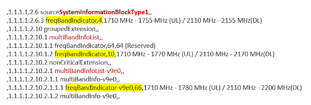
A multi-band cell consists of a default band that shall be used by UEs for initial cell selection and a set of additional frequency band carriers that typically become involved as soon as a dedicated radio bearer (DRB) for payload transmission is established in the radio connection.

The exact configuration of a multi-band cell including all available frequency bands is broadcasted in SIB 1 as shown in the example below.

Different from legacy RAN deployments where – to take the example of a LTE cell – a pair of PCI/eARFCN (Physical Cell Identity/eUTRAN Absolute Radio Frequency Number) always matches a particular ECGI (eUTRAN Cell Global Identity) the multi-band cell has many different PCI/eARFCN combinations belonging to a single ECGI as you can see in the next figure.

Now performance measurement (PM) counters for e.g. call drops are typically counted on the cell ID (ECGI) and thus, in case of mulit-band cells do not reveal on which frequency a radio link failure occurred.

However, knowing the frequency is essential to optimize the radio network and minimize connectivity problems. More detailed information must be collected to find out which of the different frequency bands performs well and which need improvement.

This becomes even more interesting if multi-band cells are used in MORAN RAN sharing scenarios.

In my next blog post I will have a closer look at this special deployment.

Related Posts:

Monday, 13 June 2022

Tutorial on 4G/5G Mobile Network Uplink Working and Challenges

People involved with mobile technology know the challenges with uplink for any generation of mobile network. With increasing data rates in 4G and 5G, the issue has become important as most of the speeds are focused on download but upload speeds are quite poor.

People who follow us across our channels know of many of the presentations we share across them from various sources, not just ours. One such presentation by Peter Schmidt looked at the uplink in details. In fact we recommend following him on Twitter if you are interested in technical details and infrastructure.

The details of his talk as follows:

The lecture highlights the influences on the mysterious part of mobile communications - sources of interference in the uplink and their impact on mobile communication as well as practices for detecting sources of RF interference.

The field strength bar graph of a smartphone (the downlink reception field strength) is only half of the truth when assessing a mobile network coverage. The other half is the uplink, which is largely invisible but highly sensitive to interference, the direction from the end device to the base stations. In this lecture, sources of uplink interference, their effects and measurement and analysis options will be explained.

Cellular network uplink is essential for mobile communication, but nobody can really see it. The uplink can be disrupted by jammers, repeaters, and many other RF sources. When it is jammed, mobile communication is limited. I will show what types of interference sources can disrupt the uplink and what impact this has on cellular usage and how interference hunting can be done.

First I explain the necessary level symmetry of the downlink (from the mobile radio base station - eNodeB to the end device) and the uplink (from the end device back to the eNodeB). Since the transmission power of the end device and eNodeB are very different, I explain the technical background to achieving symmetry. In the following I will explain the problems and possibilities when measuring uplink signals on the eNodeB, it is difficult to look inside the receiver. In comparison, the downlink is very easy to measure, you can see the bars on your smartphone or you can use apps that provide detailed field strength information etc. However, the uplink remains largely invisible. However, if this is disturbed on the eNodeB, the field strength bars on the end device say nothing. I will present a way of observing which some end devices bring on board or can be read out of the chipset with APPs. The form in which the uplink can be disrupted, the effects on communication and the search for uplink sources of disruption will complete the presentation. I will also address the problem of 'passive intermodulation' (PIM), a (not) new source of interference in base station antenna systems, its assessment, measurement and avoidance.

The slides are available here. The original lecture was in German, a dubbed video is embedded below:

If you know of some other fantastic resources that we can share with our audience, please feel free to add them in the comments.

Related Posts

Monday, 6 June 2022

2G/3G Shutdown may Cost Lives as 4G/5G Voice Roaming is a Mess

You have probably heard me a complaining about the pace of VoLTE rollout, 2G/3G shutdowns, 4G Voice roaming, etc. This post highlights all these issues coming together in a dangerous way. People often ask me why is it that it's always just me highlighting the issues. The answer is that there are other people but their voice may not reach you. In this post, I am highlighting presentations by Rudolf van der Berg, Project and programme manager at Stratix Consulting.

Let's start with Rudolf's post from LinkedIn:

Stop the shutdown of 2G and 3G networks to save lives. This is the urgent call I make today and I hope you can help me spread it! Please call on people you know in politics, regulators and emergency services to demand a stop! Call on anyone you know in the GSMA, 3GPP, handset makers (Apple, Samsung, Qualcomm, MediaTek), network builders (Ericsson, Nokia, Huawei) to re-engineer VoLTE to an interoperable standard.

Emergency calls (112, 911) should work anywhere in the world on any phone. For GSM and 3G voice calling it did. You could fly anywhere and call emergency services and in the EU we have the roaming regulation that demands calling like at home. Voice over 4G and 5G hasn't been properly standardized and isn't interoperable between networks, devices, chipsets and firmware. People need to be able to make and receive telephone calls around the world, to each other and to emergency services. Unfortunately even according to sector itself emergency services are at risk from VoLTE. A consumer today can't know whether a phone they bought will make VoLTE calls at home or abroad, nor whether it can reach emergency services. That can't be right!

So please help EENA 112 and me share this message! Thank you #eena2022 (Slide 4 contains a mistake, T-Mo USA hasn't decided on 2G shutdown yet. that is good for availability of 911, though fundamental point remains. Apologies.)

The video and slides are embedded below:

The slides contain many useful references and links, you can download directly from here.

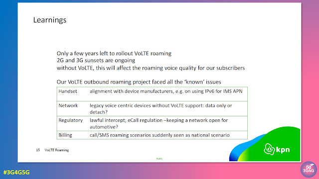
Back in April, iBASIS hosted a VoLTE and 5G Roaming Roundtable. You can watch the video here and download the presentation and whitepaper as well. It contains talks from Kaleido Intelligence, iBASIS, KPN, Bouygues Telecom and Telus. 

The slide from Dutch MNO KPN above highlights the VoLTE Roaming issues they are observing. Other operators will face this issue sooner or later as well. 

The Regulators, GSMA and 3GPP have to come together to fix this important issue for once and all so no lives are lost because of this. Hopefully someone is listening!

Related Posts

Tuesday, 31 May 2022

Transitioning from Cloud-native to Edge-Native Infrastructure

We have looked at what we mean by cloud-native in an earlier post here. Recently we also looked at edge-native infrastructure here. While we have been debating between cloud and edge for a while, in a new presentation (embedded below), Gorkem Yigit, Principal Analyst, Analysys Mason argues that the new, distributed IT/OT applications will drive the shift from cloud-native to edge-native infrastrcuture.

The talk by Gorkem on '5G and edge network clouds: industry progress and the shape of the new market' from Layer123 World Congress 2021 is as follows:

A blog post by ADVA has a nice short summary of the image on the top that was also presented at a webinar earlier. The following is an extract from that blog post: 

The diagram compares hyperscale (“cloud-native infrastructure”) on the left with hyper-localized (“edge-native infrastructure”) on the right.

  • Computing: The traditional hyperscale cloud is built on centralized and pooled resources. This approach enables unlimited scalability. In contrast, compute at the edge has limited scalability, and may require additional equipment to grow applications. But the initial cost at the edge is correspondingly low, and grows linearly with demand. That compares favorably to the initial cost for a hyperscale data center, which may be tens of millions of dollars.
  • Location sensitivity and latency: Users of the hyperscale data center assume their workloads can run anywhere, and latency is not a major consideration. In contrast, hyper-localized applications are tied to a particular location. This might be due to new laws and regulations on data sovereignty that require that information doesn’t leave the premises or country. Or it could be due to latency restrictions as with 5G infrastructure. In either case, shipping data to a remote hyperscale data center is not acceptable.
  • Hardware: Modern hyperscale data centers are filled with row after row of server racks – all identical. That ensures good prices from bulk purchases, as well as minimal inventory requirements for replacements. The hyper-localized model is more complicated. Each location must be right-sized, and supply-chain considerations come into play for international deployments. There also may be a menagerie of devices to manage.
  • Connectivity: Efficient use of hyperscale data centers depends on reliable and high-bandwidth connectivity. That is not available for some applications. Or they may be required to operate when connectivity is lost. An interesting example of this case is data processing in space, where connectivity is slow and intermittent.
  • Cloud stack: Hyperscale and hyper-localized deployments can host VMs and containers. In addition, hyper-localized edge clouds can host serverless applications, which are ideal for small workloads.
  • Security: Hyperscale data centers use a traditional perimeter-based security model. Once you are in, you are in. Hyper-localized deployments can provide a zero-trust model. Each site is secured as with a hyperscale model, but each application can also be secured based on specific users and credentials.

You don’t have to choose upfront

So, which do you pick? Hyperscale or hyper-localized?

The good news is that you can use both as needed, if you make some good design choices.

  • Cloud-native: You should design for cloud-native portability. That means using technologies such as containers and a micro-services architecture.
  • Cloud provider supported edge clouds: Hyperscale cloud providers are now supporting local deployments. These tools enable users to move workloads to different sites based on the criteria discussed above. Examples include IBM Cloud Satellite, Amazon Outposts, Google Anthos, Azure Stack and Azure Arc.

You can also learn more about this topic in the Analysys Mason webinar, “From cloud-native to edge-native computing: defining the cloud platform for new use cases.”. You can also download the slides from there after registration.

Related Posts

Monday, 23 May 2022

5G Reality Check - Data Rates

One of the common questions that we encounter is why are 5G speeds so low as we were promised 5G downlink speeds of 20 Gbps. Most people do not understand how the 5G speeds are calculated and what do they depend on. In many cases, the network won’t be capable of delivering higher speeds due to some or the other limitation. 

In a new presentation, I try to explain the theoretical speeds and compare them with real world 5G data rates and even try to map it to why these speeds are what they are. Hopefully people won't mind me adding some humour as I go along.

Video and Slides embedded below

Embedded below is the Twitter thread on Speedtests ðŸ˜‚

Related Posts

Monday, 16 May 2022

Lawful Intelligence and Interception in 5G World with Data and OTT Apps

Not long ago we looked at the 'Impact of 5G on Lawful Interception and Law Enforcement' by SS8. David Anstiss, Senior Solutions Architect at SS8 Networks gave another interesting talk on Evolving Location and Encryption Needs of LEAs in a 5G world at Telecoms Europe Telco to Techco virtual event in March.

In this talk, David provided an insight in​to how 5G is impacting lawful interception and the challenges Law Enforcement Agencies face as they work with Communication Service Providers to gather intelligence and safeguard society. While there is an overlap with the previous talk, in this video David looked at a real world example with WhatsApp. The talk also covered:

  • Real-world problems with 5GC encryption
  • 5G location capabilities and the impact on law enforcement investigations
  • Optimal solutions for both CSPs and LEAs

The video of the talk is embedded below:

Related Posts: