Showing posts sorted by relevance for query 5g. Sort by date Show all posts

Saturday 28 November 2015

5G, NFV and Network Slicing


5G networks have multifaceted requirements where the network needs to be optimised for data rate, delay and connection numbers. While some industry analysts suspect that these requirements cannot be met by a single network, vendors suggest that Network Slicing will allow all these requirements to be met by a single network.

Ericsson's whitepaper provides a good definition of what network slicing means:

A logical instantiation of a network is often called a network slice. Network slices are possible to create with both legacy platforms and network functions, but virtualization technologies substantially lower barriers to using the technology, for example through increased flexibility and decreased costs.
...
Another aspect of management and network slicing is setting up separate management domains for different network slices. This may allow for completely separate management of different parts of the network that are used for different purposes. Examples of use cases include mobile virtual network operators (MVNOs) and enterprise solutions. This kind of network slice would, in current Evolved Packet Core (EPC) networks, only cover the PDN gateway (PGW) and the policy control resource function (PCRF). However, for machine type communication (MTC) and machine-tomachine (M2M) solutions, it is likely that it would also cover the Mobile Management Entities (MMEs) and Serving Gateways (SGWs).


NGMN came out with the 5G whitepaper which touched on this subject too: 

Figure above illustrates an example of multiple 5G slices concurrently operated on the same infrastructure. For example, a 5G slice for typical smartphone use can be realized by setting fully-fledged functions distributed across the network. Security, reliability and latency will be critical for a 5G slice supporting automotive use case. For such a slice, all the necessary (and potentially dedicated) functions can be instantiated at the cloud edge node, including the necessary vertical application due to latency constraints. To allow on-boarding of such a vertical application on a cloud node, sufficient open interfaces should be defined. For a 5G slice supporting massive machine type devices (e.g., sensors), some basic C-plane functions can be configured, omitting e.g., any mobility functions, with contentionbased resources for the access. There could be other dedicated slices operating in parallel, as well as a generic slice providing basic best-effort connectivity, to cope with unknown use cases and traffic. Irrespective of the slices to be supported by the network, the 5G network should contain functionality that ensures controlled and secure operation of the network end-to-end and at any circumstance.


Netmanias has a detailed article on this topic which is quite interesting too, its available here.

Recently, South Korean operator SK Telecom and Ericsson concluded a successful trial of this technology, see here. Ericsson is also working with NTT Docomo on 5G including network slicing, see here.

Tuesday 16 August 2022

Managing 5G Signalling Storms with Service Communication Proxy (SCP)

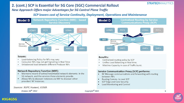
When we made our 5G Service Based Architecture (SBA) tutorial some four years back, it was based on Release-15 of the 3GPP standards. All Network Functions (NFs) simply sent discovery requests to the Network Repository Function (NRF). While this works great for trials and small scale deployments it can also lead to issues as can be seen in the slide above.

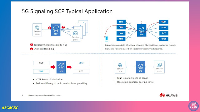
In 3GPP Release-16 the Service Communication Proxy (SCP) has now been introduced to allow the Control Plane network to handle and prioritize massive numbers of requests in real time. The SCP becomes the control point that mediates all Signalling and Control Plane messages in the network core.

SCP routing directs the flow of millions of simultaneous 5G function requests and responses for network slicing, microservice instantiation or edge compute access. It also plays a critical role in optimizing floods of discovery requests to the NRF and in overall Control Plane load balancing, traffic prioritization and message management.

A detailed whitepaper on '5G Signaling and Control Plane Traffic Depends on Service Communications Proxy (SCP)' by Strategy Analytics is available on Huawei's website here. This report was a follow on from the 'Signaling — The Critical Nerve Center of 5G Networks' webinar here.

Related Posts:

Tuesday 26 December 2017

Top 10 posts for 2017 and some other 3G4G info


Here are the top 10 3G4G blog posts (in descending order of popularity) for 2017:

  1. 5G Network Architecture and Design Update - Jan 2017
  2. 5G: Architecture, QoS, gNB, Specifications - April 2017 Update
  3. Self-backhauling: Integrated access and backhaul links for 5G
  4. 5G Core Network, System Architecture & Registration Procedure
  5. High Power / Performance User Equipment (#HPUE)
  6. IMT-2020 (5G) Requirements
  7. 5G – Beyond the Hype
  8. Variety of 3GPP IoT technologies and Market Status - May 2017
  9. 2G / 3G Switch Off: A Tale of Two Worlds
  10. 5G Research Presentation on URLLC
As you can see, 7/10 were on 5G which is probably not a surprise ðŸ˜‰.


In other news, this year I have done a lot more activities on 3G4G sites (thanks to support and encouragement from my current employer, Parallel Wireless). You can see links to all different 3G4G channels on top of the blog. I was also interviewed by TechPlayon and TechTrained (the similarity of name is just a coincidence). I was also named a key 5G influencer for 2017.

Back in 2011, I wrote the 1000th post and asked for your feedback. Here again, I would like to ask for your feedback, either on this post or on any posts. There are check-boxes for you to give instant feedback or you can add your comments in any of the posts.

I also mentioned in 2011 that the 3G4G blog will be touching 1.5 million page view mark, now in 2017 (10 years after the start of this blog), we have crossed over 9.5 million official page views (page views for first 3 years were not counted). Here is a snapshot of the stats for this and the small cells blog.


This has all been possible because of contributions from many individuals who share their presentations, knowledge and support my activities in many different ways. Thank you!

Finally, I can make mistakes too so please feel free to correct me anytime you spot me saying something wrong. I don't mind ðŸ˜Š


Related posts:

Thursday 29 September 2022

Four Ways 5G Can Improve the Battery Life of User Equipment (UE)

We have looked at different approaches in this blog and the 3G4G website on reducing the power consumption (see related posts below). In a blog post some months back, Huawei highlighted how 5G can improve the battery life of UE. The blog post mentioned four approaches, we have looked at three of them on various blogs. 

The following is from the blog post:

RRC_INACTIVE State

A UE can access network services only if it establishes a radio resource control (RRC) connection with the base station. In legacy RATs, a UE is either in the RRC_CONNECTED state (it has an RRC connection) or the RRC_IDLE state (it does not have an RRC connection). However, transitioning from the RRC_IDLE state to the RRC_CONNECTED state takes a long time, so it cannot meet the low latency requirement of some 5G services. But a UE cannot just stay in the RRC_CONNECTED state because this will consume much more UE power.

To solve this problem, 5G introduces the RRC_INACTIVE state, where the RRC connection is released but the UE context is retained (called RRC Release with Suspend), so an RRC connection can be quickly resumed when needed. This way, a UE in the RRC_INACTIVE state can access low-latency services whenever needed but consume the same amount of power as it does in the RRC_IDLE state.

DRX + WUS

Discontinuous reception (DRX) enables a UE in the RRC_CONNECTED state to periodically, instead of constantly, monitor the physical downlink control channel (PDCCH) to save power. To meet the requirements of different UE services, both short and long DRX cycles can be configured for a UE. However, when to wake up is determined by the predefined cycle, so the UE might wake up unnecessarily when there is no data scheduled.

Is there a way for a UE to wake up only when it needs to? Wake-up Signal (WUS) proposed in Release 16 is the answer. This signal can be sent before the next On Duration period (during which the UE monitors the PDCCH) so that the UE wakes up only when it receives this signal from the network. Because the length of a WUS is shorter than the On Duration Timer, using WUS to wake up a UE saves more power than using only DRX.

BWP Adaptation

In theory, working on a larger bandwidth consumes more UE power. 5G provides large bandwidths, but it is unnecessary for a UE to always work on large bandwidth. For example, if you play online mobile games on a UE, only 10 MHz of bandwidth is needed for 87% of the data transmission time. As such, Bandwidth Part (BWP) is proposed in 5G to enable UEs to work on narrower bandwidths without sacrificing user experience.

BWP adaptation enables the base station to dynamically switch between BWPs based on the UE’s traffic volume. When the traffic volume is large, a UE can work on a wide BWP, and when the traffic volume is small, the UE can work on a narrow one. BWP switching can be performed based on the downlink control information (DCI) and RRC reconfiguration messages. This ensures that a UE always works on a bandwidth that supports the traffic volume but does not consume too much power.

Maximum MIMO Layers Reduction

According to 3GPP specifications, the number of receive and transmit antennas used by a UE cannot be fewer than the maximum number of MIMO layers in the downlink and uplink, respectively. For example, when a maximum of four downlink MIMO layers are configured for a UE, the UE must enable at least four receive antennas to receive data. Therefore, if the maximum number of MIMO layers can be reduced, the UE does not have to activate as many antennas, reducing power consumption.

This can be achieved in 5G because the number of MIMO layers can be re-configured based on assistance information from UEs. After receiving a request to reduce the number of MIMO layers from a UE, the base station configures fewer MIMO layers for the UE through an RRC reconfiguration message. In this way, the UE can deactivate some antennas to save power.

Power consumption in the networks and the devices is a real challenge. While the battery capacity and charging speeds are increasing, it is also important to find ways to optimise the signalling parameters, etc. One such approach can be seen in the tweet above regarding regarding T-Mobile in The Netherlands, selectively switching off a carrier in the night and switching it back when the cell starts loading or in the morning.

We will see lot more innovations and optimisations to dynamically update the technologies, parameters, optimisations to ensure power savings wherever possible.

Related Posts

Monday 27 September 2021

Maritime Communication (MARCOM) Services over 3GPP system


Maritime Communication Services over 3GPP System is one of the topics listed in the 3GPP Release-16 summary that I summarised here.

Maritime domain, one of 5G vertical domains in 3GPP, started to be considered since 2016 to enable 3GPP systems to play the role of mobile communication platform necessary for the digitalization and mobilization of the maritime domain that bring about the Fourth Industrial Revolution of the maritime businesses as well as maritime safety.

Compared to other vertical domains, the maritime domain has the radio communication environment that 3GPP hasn’t considered in detail, which means that maritime related issues and features were not in the scope of 3GPP standardization and some of existing 3GPP enabling technologies or solutions are not able to fully support the optimized performances required by the maritime domain in a way that has been guaranteed for on-land communication. In addition, on-board mobile users in a vessel would like to experience the same rich mobile communication services as they enjoy on land.

Furthermore, it is of the view that the capacity and rate for data transmission based on legacy maritime radio communication technologies are indeed not enough for e-Navigation described in IMO Strategy Implementation Plan (SIP) or Maritime Autonomous Surface Ships (MASS), which the International Maritime Organization (IMO), a United Nations specialized agency, have been working to provide to ship.

Considering that the maritime domain is one of 5G vertical domains that 3GPP take into account in order for 5G to be able to provide enhanced mobile broadband services or massive machine-type communication services etc. everywhere anytime in the world, it is desirable to study use cases and requirements for maritime communication services over 3GPP system so that 3GPP system can be a good candidate of innovative tools to help address the information gap between users on land and users at sea as well as the maritime safety and vessel traffic management etc. that IMO intends to achieve especially in 5G era.

3GPP TR 22.819, Feasibility Study on Maritime Communication Services over 3GPP system concluded in 2018 and a report is available here. The scope of the document says:

The present document aims to support the maritime communication services between users ashore and at sea or between vessels at sea over 3GPP system that are targeted to improve maritime safety, protect the maritime environment and promote the efficiency of shipping by reducing maritime casualty caused by human error, in particular, involving small ships and fishing vessels. In addition, the outcome of the technical report is expected to narrow the information gap between mobile users on land and shipboard users on vessels at sea by making it possible to provide the mobile broadband services.

The document describes use cases and potential requirements for services between shore-based users such as authorities and shipboard users in the maritime radio communication environment over 3GPP system. In addition, it deals with use cases to support Mission Critical Services between authorities on land and authorities at sea (e.g. maritime police) as well as use cases to support the interworking between 3GPP system and the existing/future maritime radio communication system for the seamless service of voice communication and data communication between users ashore and at sea or between vessels at sea.

Analysis is also made on which legacy services and requirements from the existing 3GPP system need to be included and which potential requirements need additional work for new functions to support maritime communication services over 3GPP system.

The first 3GPP Technical Specification (TS) 22.119 covering service requirements (Stage 1) is specified for the support of maritime communication (MARCOM) over 3GPP systems.

The maritime domain, one of the 5G vertical domains in 3GPP, is moving forward with the digitalisation and mobilisation of commercial as well as safety fields. Legacy 3GPP-based technologies and solutions can be beneficial to the digitalisation and mobilisation of the maritime domain though some of the legacy 3GPP enabling technologies and solutions may not be able to fully support the performances required by the maritime domain. The maritime radio environment was not originally considered by 3GPP when the technical specifications and solutions were standardised for LTE and 5G. 

However, most of the legacy mobile services and IoT services based on capabilities of EPS and 5GS specified in 3GPP specifications are applicable to maritime usage for the support of mobile broadband services, and for the support of IoT services or machine-type communication services in a vessel at sea. 

In addition, there are service scenarios and requirements specified in 3GPP specifications based on requirements of other related vertical domains (e.g. public safety domain, automotive domain, factory automation domain, and satellite industrial domain). Some requirements derived by service scenarios from these related vertical domains are applicable to the maritime domain. Thus, it is beneficial to use 3GPP enabling technologies developed to satisfy those requirements for the maritime domain in terms of the economy of scale.

For example, satellite access is one of the 3GPP radio access networks supported over the 5G system, so it is possible to provide seamless maritime mobile services by integrating multiple access technologies including satellite access depending on the service scenarios. In addition, Vertical LAN that can replace Ethernet-based access are applicable to indoor maritime mobile services inside a vessel.

Mission Critical (MC) Services specified in 3GPP specifications are applicable to commercial and maritime safety fields. Some similarities exist between the public safety domain and the maritime domain in terms of service scenarios that are essentially the same. For example, in some situations, mobile communication services are supported in spite of disconnected networks, i.e. off-network mode, or under isolated conditions. 

However, the maritime domain also has specific situations that do not happen in other vertical domains or in the legacy ICT industrial domain. New 3GPP enabling technologies dedicated to the maritime domain can be used to address such specific situations based on requirements derived from maritime use cases. Other vertical domains may benefit from such new 3GPP enabling technologies that consider maritime domain scenarios and may need more robust technologies or solutions than those that currently exist for those vertical domains.

The following specifications are relevant for MARCOM:

  • 3GPP TS 22.119, Maritime communication services over 3GPP system
  • 3GPP TS 22.179, Mission Critical Push to Talk (MCPTT); Stage 1
  • 3GPP TS 22.280, Mission Critical (MC) services common requirements
  • 3GPP TS 22.281, Mission Critical (MC) video
  • 3GPP TS 22.282, Mission Critical (MC) data

Related Posts

Sunday 19 January 2020

2-step RACH Enhancement for 5G New Radio (NR)

5G Americas recently published a white paper titled, "The 5G Evolution: 3GPP Releases 16-17" highlighting new features in 5G that will define the next phase of 5G network deployments across the globe. It's available here. One of the sections in that details the 2-step RACH enhancement that is being discussed for a while in 3GPP. The 2-step process would supercede the 4-step process today and would reduce the lartency and optimise the signalling.


Here are the details from the 5G Americas whitepaper:

RACH stands for Random Access Channel, which is the first message from UE to eNB when it is powered on. In terms of Radio Access Network implementation, handling RACH design can be one of the most important / critical portions.
The contention-based random-access procedure from Release 15 is a four-step procedure, as shown in Figure 3.12. The UE transmits a contention-based PRACH preamble, also known as Msg1. After detecting the preamble, the gNB responds with a random-access response (RAR), also known as Msg2. The RAR includes the detected preamble ID, a time-advance command, a temporary C-RNTI (TC-RNTI), and an uplink grant for scheduling a PUSCH transmission from the UE known as Msg3. The UE transmits Msg3 in response to the RAR including an ID for contention resolution. Upon receiving Msg3, the network transmits the contention resolution message, also known as Msg4, with the contention resolution ID. The UE receives Msg4, and if it finds its contention-resolution ID it sends an acknowledgement on a PUCCH, which completes the 4-step random access procedure.

The four-step random-access procedure requires two round-trip cycles between the UE and the base station, which not only increases the latency but also incurs additional control-signaling overhead. The motivation of two-step RACH is to reduce latency and control-signaling overhead by having a single round trip cycle between the UE and the base station. This is achieved by combining the preamble (Msg1) and the scheduled PUSCH transmission (Msg3) into a single message (MsgA) from the UE, known as MsgA. Then by combining the random-access respond (Msg2) and the contention resolution message (Msg4) into a single message (MsgB) from the gNB to UE, see Figure 3.13. Furthermore, for unlicensed spectrum, reducing the number of messages transmitted from the UE and the gNB, reduces the number of LBT (Listen Before Talk) attempts.

Design targets for two-step RACH:

  • A common design for the three main uses of 5G, i.e. eMBB, URLLC and mMTC in licensed and unlicensed spectrum.
  • Operation in any cell size supported in Release 15, and with or without a valid uplink time alignment (TA).
  • Applicable to different RRC states, i.e. RRC_INACTIVE, RRC_CONNECTED and RRC_IDLE states.
  • All triggers for four-step RACH apply to two-step RACH including, Msg3-based SI request and contention-based beam failure recovery (CB BFR).

As described earlier, MsgA consists of a PRACH preamble and a PUSCH transmission, known as MsgA PRACH and MsgA PUSCH respectively. The MsgA PRACH preambles are separate from the four-step RACH preambles, but can be transmitted in the same PRACH Occasions (ROs) as the preambles of fourstep RACH, or in separate ROs. The PUSCH transmissions are organized into PUSCH Occasions (POs) which span multiple symbols and PRBs with optional guard periods and guard bands between consecutive POs. Each PO consists of multiple DMRS ports and DMRS sequences, with each DMRS port/DMRS sequence pair known as PUSCH resource unit (PRU). two-step RACH supports at least one-to-one and multiple-to-one mapping between the preambles and PRUs.

After the UE transmits MsgA, it waits for the MsgB response from the gNB. There are three possible outcomes:

  1. gNB doesn’t detect the MsgA PRACH ➡ No response is sent back to the UE ➡ The UE retransmits MsgA or falls back to four-step RACH starting with a Msg1 transmission.
  2. gNB detects MsgA preamble but fails to successful decode MsgA PUSCH ➡ gNB sends back a fallbackRAR to the UE with the RAPID (random-access preamble ID) and an uplink grant for the MsgA PUSCH retransmission ➡ The UE upon receiving the fallbackRAR, falls back to four-step RACH with a transmission of Msg3 (retransmission of the MsgA PUSCH).
  3. gNB detects MsgA and successfully decodes MsgA PUSCH ➡ gNB sends back a successRAR to the UE with the contention resolution ID of MsgA ➡ The reception of the successRAR successfully completes the two-step RACH procedure.

As described earlier, MsgB consists of the random-access response and the contention-resolution message. The random-access response is sent when the gNB detects a preamble but cannot successfully decode the corresponding PUSCH transmission. The contention resolution message is sent after the gNB successfully decodes the PUSCH transmission. MsgB can contain backoff indication, fallbackRAR and/or successRAR. A single MsgB can contain the successRAR of one or more UEs. The fallbackRAR consists of the RAPID: an uplink grant to retransmit the MsgA PUSCH payload and time-advance command. The successRAR consists of at least the contention resolution ID, the C-RNTI and the TA command.

For more details on this feature, see 3GPP RP-190711, “2-step RACH for NR” (Work-item description)

Wednesday 1 April 2020

A Look into 5G Virtual/Open RAN - Part 2

In the first blog post of this series the different virtual RAN functions, interfaces and protocols have been discussed. Now it is time to have a look at a set of procedures that are required for the establishment of an UE connection in virtual 5G RAN.

The Big Picture

In 5G standalone RAN the crucial elements for user plane payload transport of an UE connection are  GTP/IP transport tunnels and a dedicated radio bearer on the radio interface.

When looking at the 5G RAN there are two of such tunnels: one on NG-U (aka N3) that is controlled by NGAP, and one on F1-U that is controlled by F1AP - see figure 1.

On behalf  of these two tunnels payload data can be transported between the 5G core network User Plane Function (UPF) to the gNB Distributed Unit (gNB-DU) and vice versa. For the transport over the 5G RAN fronthaul (realized e.g. as eCPRI) and across the radio interface a dedicated radio bearer (DRB) for the user plane transport must be configured by the gNB Central Unit for the Control Plane (gNB-CU CP).

As in LTE it is the RRC protocol that establishes this DRB. However, due to the virtualization the different protocol layers for the air interface are also distributed and the gNB-DU is in charge of all the lower layer PHY/RLC/MAC parameters (e.g the c-RNTI), while the gNB-CU CP assigns higher layer parameters of PDCP and RRC like the DRB-ID. Since only the gNB-CU CP can send downlink RRC messages to the UE the lower layer parameters from the DU first need to be sent in uplink direction to the gNB-CU CP.

Beside this parameter exchange the F1AP is also responsible for the tunnel management of the F1-U Tunnel.

The downlink tunnel endpoint information is provided by the gNB-DU using F1AP, but the uplink tunnel endpoint terminates at the gNB-CU UP and thus, its endpoint parameters are received by the gNB-CU CP when it exchanges information with the gNB-CU UP on behalf of the E1AP protocol.

Figure 1: Network Functions, Protocols and Parameters involved in Setup of User Plane Data Transmission Resources
(click on the image to see full size)
A similar situation we see for the NG-U tunnel that is controlled by NGAP, the protocol for communication between gNB-CU CP and the Access and Mobility Management Function (AMF) in the 5G core. Neither the gNB-CU CP nor hte AMF have direct access to the NG-U tunnel endpoints. Hence, E1AP is used again to transmit the downlink tunnel parameters to the gNB-CU CP while the uplink tunnel endpoint parameters must be sent by the UPF to the Session Management Function (SMF) using the Packet Forwarding Control Protocol (PFCP) and later by the SMF to the AMF over the service-based interface where the tunnel endpoint parameters are embedded in a JavaScript Object Notation (JSON) container.

By the way, JSON is a quite generic format for exchanging and storing different kind of data. Between the AMF and the SMF JSON is used to transport Non-Access Stratum Session Management messages (defined in 3GPP 24.501).

The Ladder Diagram

Having the Big Picture in mind it is now easier to look at the ladder diagram with the individual RAN messages for UE connection setup - shown in Figure 2.

It looks complicated, because the F1AP messages carry RRC plus NAS messages in uplink and downlink direction, but when understanding the underlying logic it is easy.

Figure 2: 5G VRAN Successful UE Connection Setup
(click on the image to see full size)

The very first step (in the figure: step 0) is the random access procedure executed on the MAC layer involving the UE and the gNB-DU.

After successful random access the UE sends the NR RRC Setup Request message. This is the Initial UL RRC Message transported by the F1AP from the gNB-DU to the gNB-CU CP. Actually the F1AP carries PDCP transport blocks and inside the PDCP the NR RRC messages are found, but to keep it simple I do not show the PDCP header in the ladder diagram.

Beside RRC Setup Request there are also some other initial NR RRC messages and RRC response messages possible (see step 1 and 2).

More RRC messages are transported over F1AP until the RRC Connection establishment is complete.

The NR RRC Setup Complete message also transports the initial NAS message and the reception of this message by the gNB-CU CP triggers the setup of a F1AP UE context. The concept of UE context management in F1AP is the same as in NGAP or - when looking back into the E-UTRAN - in S1AP.

The GTP/IP transport tunnel on F1-U is established during F1AP UE Context Setup assisted by E1AP Bearer Context Setup procedure that provides the necessary tunnel endpoint parameters.

In the same manner the NG-U tunnel is established by the NGAP Initial UE Context Setup procedure.

Additional NAS messages (especially for session management) and NR RRC Reconfiguration are exchanged to establish the end-to-end UE connection through the core network. And that's it.

Related Posts:
Friday 8 December 2023

6G Global - Videos & Presentations from Mobile Korea 2023

5G Forum, South Korea organises Mobile Korea conference every year. Mobile Korea 2023 had two conferences within it, '6G Global', looking at 'Beyond Connectivity and New Possibilities', and '5G Vertical Summit', looking at 'Leading to Sustainable Society with 5G'.

I often complain about how organisations working in 6G often lack social networks skills, in this case, even the website is not very user friendly and doesn't contain a lot of details. Full marks for uploading the videos on YouTube though.

Anyway, here are the videos and presentations that were shared from the summit:

  • Opening + Keynote Session - Moderator : LEE, HyeonWoo, DanKook University
    • Standardization and Technical Trend for 6G, SungHyun CHOI, Samsung Research (video, presentation)
  • Session 1 : 6G Global Trend - Moderator : JaeHoon CHUNG, LG Electronics Inc.
    • Thoughts on standardization and Industry priorities to ensure timely market readiness for 6G, Sari NIELSEN, Nokia (video, presentation)
    • On the convergence route for 6G, Wen TONG, Huawei (video, presentation)
    • The Path from 5G to 6G: Vision and Technology, Edward G. TIEDMANN, Qualcomm Technologies  (video, presentation)
    • Shaping 6G – Technology and Services, Bo HAGERMAN, Ericsson (video, presentation)
  • Government Session
    • Keynote : Korea's 6G R&D Promotion Strategy, KyeongRae CHO, Ministry of Science and ICT (video, presentation)
  • Session 2 : 6G Global Collaboration - Moderator : Juho LEE, Samsung Electronics
  • 6G R&D and promotion in Japan, Kotaro KUWAZU, B5GPC (video, presentation)
    • Technology evolution toward beyond 5G and 6G, Charlie ZHANG, Samsung Research (video, presentation)
    • AI-Native RAN and Air Interface : Promises and Challenges, Balaji Raghothaman, Keysight (video, presentation)
    • Enabling 6G Research through Rapid Prototyping and Test LEE, SeYong, (NI) (video, presentation)
    • Global Collaborative R&D Activities for Advanced Radio Technologies, JaeHoon CHUNG, LG Electronics (video, presentation)
    • International research collaboration – key to a sustainable 6G road, Thomas HAUSTEIN, Fraunhofer Heinrich Hertz Institute (video, presentation)
    • 6G as Cellular Network 2.0: A Networked Computing Perspective, KyungHan LEE, Seoul National University (video, presentation)
    • Towards a Sustainable 6G, Marcos KATZ, University of Oulu (video, presentation)
  • Pannel Discussion : Roles of Public Domain in 6G R&D - Moderator : HyeonWoo LEE, DanKook University
  • Session 3 : 6G Global Mega Project - Moderator: YoungJo KO, ETRI
    • Sub-THz band wireless transmission and access technology for 6G Tbps data rate, JuYong LEE, KAIST (video, presentation)
    • The post Shannon Era: Towards Semantic, Goal-Oriented and Reconfigurable Intelligent Environments aided 6G communications, Emilio CALVANESE STRINATI, CEA Leti (video, presentation)
    • Demonstration of 1.4 Tbits wireless transmission using OAM multiplexing technology in the sub-THz band, DooHwan LEE, NTT Corporation (video, presentation)
    • Latest 6G research progress in China, Zhiqin WANG, CAICT (video, presentation)

If there are no links in video/presentation than it hasn't been shared.

Related Posts

Tuesday 24 September 2019

When does your 5G NSA Device Show 5G Icon?


After I wrote about the 5G Icon Display back in February, I received lots of other useful and related materials, mostly from 3GPP standards delegates. Based on this updated information, I created a presentation and video called 'The 5G Icon Story'. Only recently did I realize that I didn't add it to the blog. So here it is.

And for people who are impatient and directly want to jump to the main point, it's UpperLayerIndication in SIB 2 as can be seen above.

The slides and video is embedded below.


Related Posts:


Saturday 29 June 2019

Presentations from ETSI Security Week 2019 (#ETSISecurityWeek)


ETSI held their annual Security Week Seminar 17-21 June at their HQ in Sophia Antipolis, France. All the presentations are available here. Here are some I think the audience of this blog will like:


Looks like all presentations were not shared but the ones shared have lots of useful information.


Related Posts:

Sunday 2 June 2019

Couple of talks by NTT Docomo on 5G and Beyond (pre-6G)


The Japanese operator, NTT Docomo is a very bold MNO. Not only do they do interesting research but they are very open about what they have been doing and share it publicly. For example, last month they announced development of a safe, blade-free drone propelled by Ultrasonic Vibrations (tweet). This was just amazing as it has a potential to use drones in many new areas where the conventional drones are deemed too dangerous. This is why I was very pleased to see couple of talks by Docomo available online.

The first one is by Takehiro Nakamura, SVP and General Manager of the 5G Laboratories in NTT DOCOMO, Inc. at the 6G Summit in Finland. Slides available here. Video embedded below


The next one is by Seizo Onoe, Chief Technology Architect, NTT DOCOMO, INC. and President, DOCOMO Technology, Inc. from Brooklyn 5G Summit. Unfortunately the slides are not shared but the video is worth a watch below.


Related Posts:

Friday 10 March 2023

How many Cell Sites and Base Stations Worldwide?

I wrote a blog post on this topic nearly three years back on the Operator Watch Blog here. That post is very handy as every few months someone or other asks me about this number. Here is a slightly updated number, though I am not confident on its accuracy. 

Gabriel Brown, analyst at Heavy Reading shares this chart above in the annual online Open RAN Digital Symposium. Based on the chart above, there are 7 million physical sites and 10 million logical sites. As there are many sites hosting infrastructure from multiple operators, the number of logical sites are more than the number of physical sites.

Again, most of the sites have distributed RAN (D-RAN) so there may be one or more base stations (baseband unit or BBU) and each base station can serve one or more radios. See links at the bottom for tutorials on these topics.

China Tower had nearly 2.1 million telecom towers installed with 3.36m tower tenants at end of 2022. An MIIT minister said that China's operators will deploy 600k 5G base stations in 2023, taking total to 2.9m.

The number of 5G radios in India just crossed 100,000 according to latest data released by the Department of Telecommunications. A base station generally manages multiple radios so not sure how many base stations would be there for 5G and even for older Gs.

In South Korea, according to the Ministry of Science and ICT and the mobile communication industry, as of December 2021, had 460,000 5G wireless stations of which, base stations accounted for 94% of the total, or 430,000 units, while repeaters only accounted for 30,000 units, or 6%.

Light Reading reported in September 2022 that there are nearly 419,000 cell sites across the US, according to the newest figures from CTIA. 

China and USA are roughly the same size so you can see how China is ensuring their mobile networks provide the best QoE. It should also be noted that the population of China is over four times that of the USA. On the other hand, India and China have the same population but India is one third the size of China roughly.

Related Posts:

Wednesday 5 June 2019

New Tutorial on 5G Spectrum


We made a new tutorial on 5G spectrum. It's in 2 different formats. Short version (~13 mins) or Long version (~31 mins). Instead of embedding the slides/videos here, I am providing links to the 5G section on 3G4G page below.

Short Version (~13 mins) - click here

Long Version (~31 mins) - click here


Related posts:


Monday 2 November 2020

Lawful Intercept in 5G Networks

Mats Näslund is a cryptologist at the National Defence Radio Establishment outside Stockholm, an agency under the Swedish dept. of defence. As part of his work, he represents Sweden in technical LI standardization in 3GPP. Mats also has a part time appointment as adjunct professor at KTH. Her recently delivered a HAIC Talk on Lawful Intercept in 5G Networks. HAIC Talks is a series of public outreach events on contemporary topics in information security, organized by the Helsinki-Aalto Institute for Cybersecurity (HAIC).


The following is the description from HAIC website:

Our societies have been prospering, much due to huge technological advances over the last 100 years. Unfortunately, criminal activity has in many cases also been able to draw benefits from these advances. Communication technology, such as the Internet and mobile phones, are today “tools-of-the-trade” that are used to plan, execute, and even hide crimes such as fraud, espionage, terrorism, child abuse, to mention just a few. Almost all countries have regulated how law enforcement, in order to prevent or investigate serious crime, can sometimes get access to meta data and communication content of service providers, data which normally is protected as personal/private information. The commonly used term for this is Lawful Interception (LI). For mobile networks LI is, from a technical standpoint, carried out according to ETSI and 3GPP standards. In this talk, the focus will lie on the technical LI architecture for 5G networks. We will also give some background, describing the general, high-level legal aspects of LI, as well as some current and future technical challenges.

The slides are available here.

Related Posts:

Sunday 29 May 2016

5G & 802.11ax


Samsung is one of the 5G pioneers who has been active in this area for quite a while, working in different technology areas but also making results and details available for others to appreciate and get an idea on what 5G is all about. 

I published a post back in 2014 from their trials going on then. Since then they have been improving on these results. They recently also published the 5G vision paper which is available here and here.


In the recent 5G Huddle, Raj Gawera from Samsung gave an excellent presentation (below) on the topic of "The future connected world". 


What we really liked is how closely 5G and 802.11ax can be considered aligned, not only in terms of requirements but also the roadmap.

Anyway, here is the presentation embedded below. Let me know what you think in the comments below.


Wednesday 12 February 2020

AI your Slice to 5G Perfection


Back in November, The Enhanced Mobile Broadband Group in CW (Cambridge Wireless) held an event on 'Is automation essential in 5G?'. There were some thought provoking presentations and discussions but the one that stood out for me was by Dan Warren from Samsung


The slides are embedded below but I want to highlight these points:
  • Some Network Functions will be per slice whereas others will be multi-slice, the split may not be the same for every slice
  • Two slices that have the same 'per slice vs multi-slice' functional split may be different network hardware topologies
  • Enterprise customers will likely want a 'service' contract that has to be manifested as multiple slices of different types. 
  • Physical infrastructure is common to all slices
The last point is very important as people forget that there is a physical infrastructure that will generally be common across all slices.

Again, when you apply Artificial Intelligence (AI) to optimize the network functions, does it do it individually first and then end-to-end and if this is applied across all slices, each of which may have a different functionality, requirement, etc. How would it work in practice?


As Dan says in his tweet, "It is hard to implement AI to optimise a point solution without potentially degrading the things around it.  Constantly being pushed to a bigger picture view => more data => more complexity"

Let me know what you think.

Related Posts: